


One of the most common uses for microcontrollers is for interfacing to various sensors to monitor the world around you. With an Arduino board you can read the value from a temperature sensor and output it to a computer in a matter of minutes. But what if your Arduino and sensor needs to be remotely located and it isn’t practical for it to be tethered to a computer? One solution is to use a data logger.
By storing the measurements read from your sensors, together with a time stamp, these can then be read back into your computer at a later date for analysis. Most Arduino boards contain an area of non-volatile memory for storage, but this area is relatively small and would soon fill up with measured data. A better solution is to take advantage of the cheap and massive storage potential provided by SD cards.
The Arduino development environment already provides a built-in library which supports writing to these types of cards via a suitable hardware interface and with the addition of a data logger shield you can turn your Arduino into a data logger in no time at all. In this tutorial we are going to take advantage of a data logger shield to demonstrate how easy it is to use your Arduino to monitor the temperature sensed by an LM35 temperature sensor and store it together with a time-stamp to a standard SD card.
The shield itself provides everything we need other than the SD card for storage and the LM35 temperature itself.
You will need:
A suitable Arduino board such and an Uno
SD card or microSD card with adaptor
MAKING THE CONNECTIONS
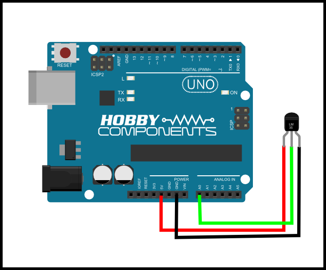
You can reference the above image for how to connect the LM35 to the headers on the Arduino or data logger shield. The shield has a prototyping area so you have the option of using this to solder the sensor directly to the shield. If you want to mount your sensor remotely, just connect straight to the shields headers via a jumper cable.
Cable one:Â Connect the first cable to pin 1 of the LM35DZ and the other end to the 5V Pin on your data logger shield.
Cable two:Â Connect the second cable to pin 2 of the LM35DZ and the other end to the analogue pin 0 on your data logger shield (marked A0 on your uno and 0 on the shield).
Cable three:Â Connect pin 3 on the LM35DZ to the pin labelled GND on your data logger shield.
Once all connections are made you can go ahead and plug the shield into your Arduino board and then connect your Arduno to your computer.
Now for the software part:
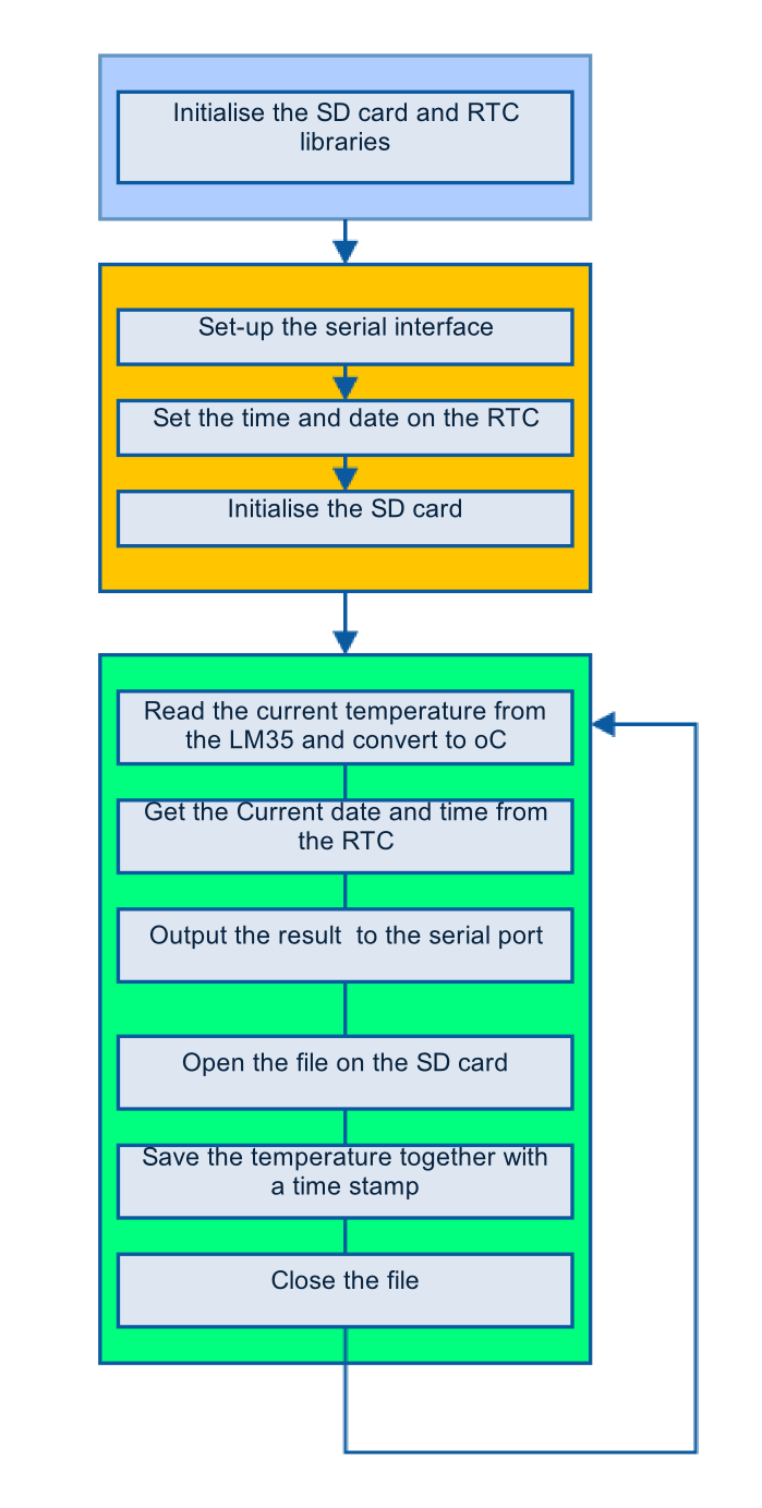
To log the temperature we will be repeating the following steps in software once every second:
- Read the current date and time.
- Read the current temperature from the LM35 connected to the analogue pin A0 and convert it into 0C
- Open a file on the SD card.
- Save the measurement together with the date and time to the end of the file.
- Close the file.
 To create a time stamp to be stored along with our measurements we need to access the Real Time Clock (RTC) on the shield. To do this we have written a library (HCRTC) which makes setting and reading the current time as straight forward as possible. To run the sketch you will need to install this library to your Arduino’s IDE.
The HCRTC library and information on how to use it can be found on our support forum here. Just download and copy it to your Arduino library folder in the same way you would any other library.
THE SKETCH
Simply copy and paste the sketch below, or download it here.
[cpp]
/* FILE: Data_Logger_Shield_HCARDU0093_Example
DATE: 24/02/15
VERSION: 0.1
REVISIONS:
24/02/15 Created version 0.1
This is an example of how to use the Hobby Components data logger shield
(HCMODU0093). This shield contains a battery backed DS1307 real time clock
and an SD card interface. This allows any sensor data read by your Arduino
to be stored with an accurate time stamp to an SD card. In this example sketch
we will continually read the value of an LM35 temperature sensor and store the
result together with the current time and date to a CSV file. This file can then
be loaded into a spreadsheet such as Excel or Open Office.
To use this sketch you will require the HCTRC library which is available for
download in the software section of our support forum. You will also need to
connect an LM35 temperature sensor as follows:
LM35…..Arduino
Pin 1….+5V
Pin 2….Analogue pin A0
Pin 3….GND
You may copy, alter and reuse this code in any way you like, but please leave
reference to HobbyComponents.com in your comments if you redistribute this code.
This software may not be used directly for the purpose of promoting products that
directly compete with Hobby Components Ltd’s own range of products.
THIS SOFTWARE IS PROVIDED "AS IS". HOBBY COMPONENTS MAKES NO WARRANTIES,
WHETHER EXPRESS, IMPLIED OR STATUTORY, INCLUDING, BUT NOT LIMITED TO, IMPLIED
WARRANTIES OF MERCHANTABILITY AND FITNESS FOR A PARTICULAR PURPOSE, ACCURACY OR
LACK OF NEGLIGENCE. HOBBY COMPONENTS SHALL NOT, IN ANY CIRCUMSTANCES, BE LIABLE
FOR ANY DAMAGES INCLUDING, BUT NOT LIMITED TO, SPECIAL, INCIDENTAL OR
CONSEQUENTIAL DAMAGES FOR ANY REASON WHATSOEVER. */
/* Include the wire library */
#include <Wire.h>
/* Include the Hobby Components RTC library */
#include <HCRTC.h>
/* Include the standard SD card library */
#include <SD.h>
/* The RTC has a fixed addresses of 0x68 */
#define I2CDS1307Add 0x68
/* DIO pin used to control the SD card CS pin */
#define SD_CS_DIO 10
/* Define the analogue pin used to read the temperature sensor (A0) */
#define LM35Pin 0
/* Create an instance of HCRTC library */
HCRTC HCRTC;
/* Create an instance of the standard SD card library */
File SDFile;
/* This will store the current temperature reading */
float Temperature;
void setup()
{
/* Initialise the serial port */
Serial.begin(9600);
/* Set the analogue reference used by the ADC inputs
to the internal 1.1V reference */
analogReference(INTERNAL);
/* Set the SD card CS pin to an output */
pinMode(SD_CS_DIO, OUTPUT);
/* Use the RTCWrite library function to set the time and date.
Parameters are: I2C address, year, month, date, hour, minute, second,
day of week. You would normally only need to do this once */
HCRTC.RTCWrite(I2CDS1307Add, 15, 2, 24, 14, 21, 0, 2);
/* Initialise the SD card */
if (!SD.begin(SD_CS_DIO))
{
/* If there was an error output this to the serial port and go no further */
Serial.println("ERROR: SD card failed to initialise");
while(1);
}else
{
Serial.println("SD Card OK");
}
}
/* Main Loop */
void loop()
{
/* Read the LM35 connected to the analogue pin and convert to oC */
Temperature = analogRead(LM35Pin) / 9.31;
/* Read the current time from the RTC module */
HCRTC.RTCRead(I2CDS1307Add);
/* Lets output this data to the serial port */
Serial.print(HCRTC.GetDateString());
Serial.print(", ");
Serial.print(HCRTC.GetTimeString());
Serial.print(", ");
Serial.println(Temperature);
/* Open the data.csv file to save our data to.
If the file already exists it will just tag our new data onto the end of it */
SDFile = SD.open("data.csv", FILE_WRITE);
if (SDFile)
{
SDFile.print(HCRTC.GetDateString());
SDFile.print(", ");
SDFile.print(HCRTC.GetTimeString());
SDFile.print(", ");
SDFile.println(Temperature);
SDFile.close();
}
/* Wait a second before reading again */
delay(1000);
}
[/cpp]
Insert an SD card into the data logger shield and upload the sketch to your Arduino. Open the serial monitor window in your Arduino IDE by going to Tools->Serial Monitor. If all is well you should see something similar to the window below. If you see garbled text then check that you have the baud rate set to 9600 in the bottom right of the window. If the sketch complains that it can’t access the SD card then check the formatting of your card. It should be either FAT16 or FAT32. Sometimes cards that are formatted by the factory can cause problems. If you still can’t get the sketch to access the card try reformatting it with your computer.
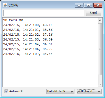
If the sketch is able to write to the SD card OK, it will create a CSV file called ‘data.csv’. The file is just a standard text file that can be read by any text editor, but it can also be read into any spreadsheet that can read CSV files, allowing you to graph your logged data. Once the file has been opened the sketch will start saving the sensor reading to it. If the file already exists it will just append the new reading onto the end. Here is what the contents of the data.csv file should look like:

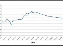
When loaded into a spreadsheet we can easily graph our sensor data:
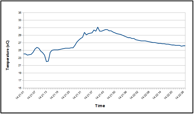
Example graph created using Open Office Calc
One final note…..
You will notice that each time you run this example sketch the data logger time always resets to the same time. This is because in our sketch we always reset the RTC’s time with the following line:
HCRTC.RTCWrite(I2CDS1307Add, 15, 2, 24, 14, 21, 0, 2);
Each time we reset the Arduino the above line gets executed and the time and date get reset to 14:21:00 / 24th Febuary 2015 . You can change this line to set the RTC to the correct time and date. The format is as follows:
HCRTC.RTCWrite(I2CDS1307Add, <DAY>, <MONTH>, <YEAR>, <HOUR>, <MIN>, <SEC>, <DAY OF WEEK>);
Once you have changed this and set the RTC to the correct time and date you can then remove this line from the sketch and re-flash it to your Arduino. As long as the data logger has a good battery it will never lose the correct time and date, even when power to the shield is removed.


Hi. I”m new to this tryed your sketch but get stuck at this error
Arduino: 1.6.12 (Windows 10), Board: “Arduino/Genuino Uno”
HCRTC_Example:61: error: ‘SDLib::File SDFile’ redeclared as different kind of symbol
File SDFile;
^
In file included from C:\Users\User\AppData\Local\Temp\arduino_modified_sketch_699565\HCRTC_Example.ino:46:0:
C:\Program Files (x86)\Arduino\libraries\SD\src/SD.h:119:24: note: previous declaration ‘typedef class SDLib::File SDFile’
typedef SDLib::File SDFile;
^
C:\Users\User\AppData\Local\Temp\arduino_modified_sketch_699565\HCRTC_Example.ino: In function ‘void loop()’:
HCRTC_Example:116: error: expected unqualified-id before ‘=’ token
SDFile = SD.open(“data.csv”, FILE_WRITE);
^
HCRTC_Example:118: error: expected primary-expression before ‘)’ token
if (SDFile)
^
HCRTC_Example:120: error: expected unqualified-id before ‘.’ token
SDFile.print(HCRTC.GetDateString());
^
HCRTC_Example:121: error: expected unqualified-id before ‘.’ token
SDFile.print(“, “);
^
HCRTC_Example:122: error: expected unqualified-id before ‘.’ token
SDFile.print(HCRTC.GetTimeString());
^
HCRTC_Example:123: error: expected unqualified-id before ‘.’ token
SDFile.print(“, “);
^
HCRTC_Example:124: error: expected unqualified-id before ‘.’ token
SDFile.println(Temperature);
^
HCRTC_Example:125: error: expected unqualified-id before ‘.’ token
SDFile.close();
^
exit status 1
‘SDLib::File SDFile’ redeclared as different kind of symbol
This report would have more information with
“Show verbose output during compilation”
option enabled in File -> Preferences.
Just worked it out, lower case s in SD fike
Is it possible to substitute the lm35 for a Thermistor? I’ve been trying to play with the code to get it to work
Yes you could do that but there are a few things you’ll need to do:
Firstly you will probably have to connect your thermistor to the 5V supply via a resistor and then connect the center point to the Arduino’s analogue pin. For example if you have a 10K thermistor you could connect it like this:
5V—->10K resistor—->PIN A0—-> Thermistor—->GND
You would also need to configure the analogue pin to reference to 5V instead of its internal 1.1V reference. You can simply do this by removing the following line from the sketch:
analogReference(INTERNAL);
You will then of course have to convert the value read from the analogue pin to to the correct temperature.
Hi, i am doing data logging using HCRTC library. But i want to save the file by using the date-time format(eg. 9/10/18_T_06:05:43.cvs) but don’t know how to use the HCRTC1.RTCRead(I2CDS1307Add) to use it for making a file name as format of
date-time .cvs file
I think the easiest way would be to use the GetDay(), GetHour(), GetMinute(), GetSecond(), ect (see here for complete list http://forum.hobbycomponents.com/viewtopic.php?f=58&t=1357) library functions to get the individual values for date and time and then add them into a pre-formatted null terminated character array (http://www.cplusplus.com/doc/tutorial/ntcs/). So say you want a file name in the format HH_MM_SS.csv you could do something like this:
[cpp]
void loop()
{
char FileName[] = {‘0′,’0′,’_’,’0′,’0′,’_’,’0′,’0′,’.’,’c’,’s’,’v”\0’};
byte Hour = HCRTC.GetHour()
byte Min = HCRTC.GetMinute()
byte Sec = HCRTC.GetSecond()
FileName[0] = DigToASCII(Hour, 10);
FileName[1] = DigToASCII(Hour, 1);
FileName[3] = DigToASCII(Min, 10);
FileName[4] = DigToASCII(Min, 1);
FileName[6] = DigToASCII(Sec, 10);
FileName[7] = DigToASCII(Sec, 1);
Serial.println(FileName);
while(1);
}
char DigToASCII(byte Value, byte Unit)
{
return ((Value / Unit) % 10) + 48;
}
[/cpp]
You can modify this example to also include the date.