


In this final part of the series we will use three SSD1306 128×64 pixel OLED display modules to create the kind of display you’d find on the concourse of a mid-sized railway station. Two screens will detail departures, the third will feature a clock and train arrivals. By pulling together the code from this series, one nano will drive all three modules.
The first challenge to tackle is displaying our departures across two screens.
Dual Departure Display
Six departures are going to be displayed across two screens. The first three scheduled departures will appear on the first screen with the following three positioned on the second screen. We can continue to use the displayDeparture() function from the previous part of the series. The code of this function requires a modification to enable it to display the correct trains on two screens.
When the function is called it will now be passed two values. Along with row it will also be passed a number for the screen. To keep this logical the number for the screen will be either 1 or 2.
void displayDeparture(byte row, int screen)We are calculating which train to display by adding the current row to the nextDepature value. If row is now on the second screen then we need to add a further 3 to this. To enable the use of two displays, the code to calculate “train” is modified as follows:
byte train;
train = row + nextDeparture;
if (screen == 2) train += 3;
if (train >= NUMBER_OF_DEPARTURES)
{
    train = train - NUMBER_OF_DEPARTURES;
}
The loop() now needs to create displays for two screens. We will enclose our display generating code in a for loop of 2. As well as creating both screens we will send the value of the for loop (1 or 2) to displayDepartures() to determine which rows will appear on which screen.
for (int screen = 1; screen <= 2; screen++)
{
  HCuOLED.ClearBuffer();
  for (int i = 0; i < departureRows; i++)
  {
    displayDeparture(i, screen);
  }
  HCuOLED.Refresh();
}
A Three Screen Display
It’s time to wire up another two SSD1306 Display Modules to our nano. They will both need 5V and GND wires. DO (SCK) and D1 (SDA) need to be connect to pins 13 and 11 respectively, the same as our first module. Each module will have it’s own dedicated pins for each of RST (reset), DC (data/command) and CS (chip select). These are wired to any unused pins on the nano, apart from pin 12, don’t use 12! We are going to use the same pins as defined in the HCuOLED_Multiple_Displays example.
/* Module 1 digital pins */
#define CS_DI1 10
#define DC_DI1 9
#define RST_DI1 8

/* Module 2 digital pins */
#define CS_DI2 7
#define DC_DI2 6
#define RST_DI2 5

/* Module 3 digital pins */
#define CS_DI3 4
#define DC_DI3 3
#define RST_DI3 2
When we are using more than one screen we have to create an instance of the library for each display, using the pins for RST_DI , DC_DI and CS_DI we have just defined.
/* Create an instance of the library for each display */
HCuOLED HCuOLED1(SSD1306, CS_DI1, DC_DI1, RST_DI1);
HCuOLED HCuOLED2(SSD1306, CS_DI2, DC_DI2, RST_DI2);
HCuOLED HCuOLED3(SSD1306, CS_DI3, DC_DI3, RST_DI3);
Note that these defines and instances replace this previous code that we were using with a single display.
#define CS_DI 10
#define DC_DI 9
#define RST_DI 8
/* Create an instance of the library for the display */
HCuOLED HCuOLED(SSD1306, CS_DI, DC_DI, RST_DI);
Elsewhere in the code we need to modify all the calls to HCuOLED so they call HCuOLED1.
With these changes our first display will receive the information for both of the departure boards. The next modification to the code will be to send the information for our second screen to the second instance of our module. And due to a quirk in the library we are using, this is very simple.
Development boards such as Uno’s and Nano’s have very very limited memory. The Buffer we are using to write our pixels to the screen uses a big chunk of this memory. Our current code is using 75% of it, which is enough for the Arduino IDE to show a low memory warning when the code is verified.
There isn’t enough memory to create more than one buffer, so there is only one. This single buffer is used for all three modules.
When using multiple modules we have to work though a sequence. First we clear the buffer, build up the data and use the Refresh() function to display it on module one. We repeat the process of clearing and building the buffer before we “Refresh” it to module two. Then we do the same to our third module.
Because the clearing and building of the buffer takes place in the one buffer, it doesn’t matter if we use HCuOLED1 or HCuOLED2 when filling the buffer. It is only when we use the Refresh() function that we have to be specific about which display we are intending to use. And this is the quirk that makes our life simple. All the references to HCuOLED1 in displayDeparture() can remain unchanged.
To send our departures to the correct screen we need to make a small change to when we call Refresh() from the loop().
if (screen == 1)  HCuOLED1.Refresh();
else              HCuOLED2.Refresh();
When screen is 1 we refresh our first module. When it isn’t we refresh the second.
In setup() we will ensure that each of our modules are Reset() at power up by adding calls to screens 2 and 3.
  /* Reset the displays */
  HCuOLED1.Reset();
  HCuOLED2.Reset();
  HCuOLED3.Reset();
The code to drive our two departure screens from one Nano:
#include "HCuOLED.h"
#include "SPI.h"

// These connect to the CS, DC, and RST pins on the display.
/* Module 1 digital pins */
#define CS_DI1 10
#define DC_DI1 9
#define RST_DI1 8

/* Module 2 digital pins */
#define CS_DI2 7
#define DC_DI2 6
#define RST_DI2 5

/* Module 3 digital pins */
#define CS_DI3 4
#define DC_DI3 3
#define RST_DI3 2


const byte NUMBER_OF_DEPARTURES = 6;
byte departureRows = 3;
byte nextDeparture;

/* clock stuff */
byte h=13;
byte m=12;
byte s=48;

unsigned long nextSecond;

/* Create an instance of the library for each display */
HCuOLED HCuOLED1(SSD1306, CS_DI1, DC_DI1, RST_DI1);
HCuOLED HCuOLED2(SSD1306, CS_DI2, DC_DI2, RST_DI2);
HCuOLED HCuOLED3(SSD1306, CS_DI3, DC_DI3, RST_DI3);

struct TrainDeparture
{
  byte minutes;
  byte platform;
  char *destination;
  char *stops;
  byte scroll;
  int xPos;
  byte hours;
  unsigned long scrollReset;
  unsigned long scrollWait;

  void setup()
  {
    if (minutes > m)  hours = h;
    else              hours = h+1;
    if (hours==24)    hours=0;
  }

  void update()
  {
    if (minutes == m)
    {
      hours += 1;
      if(hours == 24) hours = 0;
      nextDeparture += 1;
      if (nextDeparture == 6) nextDeparture = 0;
    }
  }
  void scrollStops()
  {
    if (millis() > scrollWait)
    {
      scrollWait = millis() + 100;
      if (xPos > -scroll)
      {
        xPos -= 1;
        scrollReset = millis() + 2000;
      } else {
        if (millis() > scrollReset)
        {
          xPos = 0;
          scrollWait = millis() + 2000;
        }
      }
    }
  }
};

TrainDeparture departures[NUMBER_OF_DEPARTURES] = {
  {11, 1, "Sheffield", "Chesterfield and Sheffield"},
  {14, 3, "Nottingham", "Hucknall, Bullwell and Nottingham"},
  {28, 1, "Amblethorpe", "Barnmouth, Amblethorpe"},
  {40, 2, "Newcastle", "Sheffield, Leeds, York, Darlington and Newcastle", 80},
  {49, 4, "Blyth", "Ledston and Blyth"},
  {58, 1, "Amblethorpe", "Barnmouth, Amblethorpe"}
};


void displayDeparture(byte row, int screen)
{
  const byte ROW_HEIGHT = 22;
  byte train;
  train = row + nextDeparture;
  if (screen == 2) train += 3;
  if (train >= NUMBER_OF_DEPARTURES)
  {
      train = train - NUMBER_OF_DEPARTURES;
  }
  row = row * ROW_HEIGHT;
  HCuOLED1.SetFont(sharpsharp_6pt);

  HCuOLED1.Cursor(0, row);
  if (departures[train].hours>9)
  {
    HCuOLED1.Print(departures[train].hours);
  } else if (departures[train].hours==0)
  {
    HCuOLED1.Print("00");
  } else {
    HCuOLED1.Print("0");
    HCuOLED1.Cursor(4, row);
    HCuOLED1.Print(departures[train].hours);
  }

  HCuOLED1.Cursor(9, row);
  HCuOLED1.Print(":");

  HCuOLED1.Cursor(11, row);
  if (departures[train].minutes>9)
  {
    HCuOLED1.Print(departures[train].minutes);
  } else if (departures[train].minutes==0)
  {
    HCuOLED1.Print("00");
  } else {
    HCuOLED1.Print("0");
    HCuOLED1.Cursor(16, row);
    HCuOLED1.Print(departures[train].minutes);
  }

  HCuOLED1.Cursor(24, row);
  HCuOLED1.Print(departures[train].destination);

  HCuOLED1.Cursor(91, row);
  HCuOLED1.Print(departures[train].platform);

  HCuOLED1.Cursor(100, row);
  HCuOLED1.Print("On Time");

  HCuOLED1.SetFont(sharpsharp_5pt);
  HCuOLED1.Cursor(0,(row+8));
  HCuOLED1.Print("calling at");

  if (departures[train].scroll > 0)
  {
    departures[train].scrollStops();
  }
  HCuOLED1.Cursor(departures[train].xPos, row+14);
  HCuOLED1.Print(departures[train].stops);

}

void setup()
{
  /* Reset the displays */
  HCuOLED1.Reset();
  HCuOLED2.Reset();
  HCuOLED3.Reset();

  for (int i = 0; i < NUMBER_OF_DEPARTURES; i++)
  {
    departures[i].setup();
  }
  for (int i = 0; i < NUMBER_OF_DEPARTURES; i++)
  {
    if (departures[i].minutes > m)
    {
      nextDeparture = i;
      break;
    }
  }
}
void loop()
{
  for (int screen = 1; screen <= 2; screen++)
  {
    HCuOLED1.ClearBuffer();
    for (int i = 0; i < departureRows; i++)
    {
      displayDeparture(i, screen);
    }
    if (screen == 1)  HCuOLED1.Refresh();
    else		          HCuOLED2.Refresh();
  }


  if (millis() >= nextSecond)
  {
    s=s+1;
    nextSecond = millis() + 1000;
  }

  if(s==60)
  {
    s=0;
    m=m+1;
    departures[nextDeparture].update();
  }
  if(m==60)
  {
    m=0;
    h=h+1;
  }
  if(h==24) h=0;

}
With both our departure screens up and running our attention now turns to the clock and train arrivals, which we will display on the third screen.
Arrivals and Clock
The final stage of creating our passenger information display is to merge in code from our arrivals display. As we do this there are two things to note. We used the same code for our clock data in both, so we don’t need to copy that across. Our arrivals board code is written for a single display. References to HCuOLED need to be replaced by HCuOLED3 to ensure they display on the third screen.
We will add our defines and declarations at the start of our sketch, placing them after the defining of the pins.
#define onTime 0
#define cancelled 1
#define arrived 2
#define noPlatform 3
#define delayed 4
#define bus 5

const byte NUMBER_OF_ARRIVALS = 6;
byte arrivalRows = 5;
byte nextArrival;
Add the TrainArrival struct after the TrainDeparture struct.
struct TrainArrival
{
  byte minutes;
  byte platform;
  char *origin;
  byte state;  //  onTime, cancelled, delayed, noPlatform, arrived, bus
  byte hours;


    void setup()
  {
    if (minutes > m)  hours = h;
    else              hours = h+1;
    if (hours==24)    hours=0;
  }
  void update()
  {
    byte randNumber;
    randNumber = random(10);
    if (m == minutes-1)
    {
      if (state == onTime)
      {
        if (randNumber < 5)
        {
          state = arrived;
        }
      }
    }
    if (state == noPlatform) state = onTime;

    if (m == minutes+1)
    {
      state = onTime;
      if(randNumber >= 6) state = noPlatform;
      if(randNumber == cancelled) state = cancelled;
      if(randNumber == bus) state = bus;
      if(randNumber == delayed) state = delayed;

      hours += 1;
      if(hours == 24) hours = 0;

      nextArrival += 1;
      if (nextArrival == 6) nextArrival = 0;
    }
  }
};
Add declaration of arrivals after the similar declaration of departures.
TrainArrival arrivals[NUMBER_OF_ARRIVALS] = {
  {13, 1, "Amblethorpe", delayed},
  {17, 4, "Blyth"},
  {26, 2, "Newcastle", cancelled},
  {44, 1, "Amblethorpe"},
  {54, 2, "Sheffield", noPlatform},
  {56, 3, "Nottingham", bus},
};
Having replaced HCuOLED with HCuOLED3 add the displayArrival() and displayClock() functions after the displayDepartures() function.
void displayArrival(byte row)
{
  const byte ROW_HEIGHT = 7;
  byte train;
  train = row + nextArrival;
  if (train >= NUMBER_OF_ARRIVALS)
  {
      train = train - NUMBER_OF_ARRIVALS;
  }
  row = row * ROW_HEIGHT;
  row = row + 30;
  HCuOLED3.SetFont(sharpsharp_5pt);
  HCuOLED3.Cursor(0, 22);
  HCuOLED3.Print("Arrivals");

  HCuOLED3.Cursor(0, row);
  HCuOLED3.Print(arrivals[train].origin);

  HCuOLED3.Cursor(64, row);
  if (arrivals[train].hours>9)
  {
    HCuOLED3.Print(arrivals[train].hours);
  } else if (arrivals[train].hours==0)
  {
    HCuOLED3.Print("00");
  } else {
    HCuOLED3.Print("0");
    HCuOLED3.Cursor(68, row);
    HCuOLED3.Print(arrivals[train].hours);
  }

  HCuOLED3.Cursor(72, row);
  HCuOLED3.Print(":");

  HCuOLED3.Cursor(74, row);
  if (arrivals[train].minutes>9)
  {
    HCuOLED3.Print(arrivals[train].minutes);
  } else if (arrivals[train].minutes==0)
  {
    HCuOLED3.Print("00");
  } else {
    HCuOLED3.Print("0");
    HCuOLED3.Cursor(79, row);
    HCuOLED3.Print(arrivals[train].minutes);
  }


  if (arrivals[train].state != cancelled)
  {
    HCuOLED3.Cursor(88, row);
    if (arrivals[train].state == noPlatform)
    {
      HCuOLED3.Print("-");
    } else if (arrivals[train].state == bus)
    {
      HCuOLED3.Cursor(85, row);
      HCuOLED3.Print("Bus");
    } else
    {
      HCuOLED3.Print(arrivals[train].platform);
    }
  }

  if (arrivals[train].state == cancelled)
  {
    HCuOLED3.Cursor(95, row);
    HCuOLED3.Print("Cancelled");
  } else if (arrivals[train].state == arrived)
  {
    HCuOLED3.Cursor(104, row);
    HCuOLED3.Print("Arrived");
  } else if (arrivals[train].state == delayed)
  {
    HCuOLED3.Cursor(100, row);
    HCuOLED3.Print("Delayed");
  } else
  {
    HCuOLED3.Cursor(100, row);
    HCuOLED3.Print("On Time");
  }
}

void displayClock()
{
  byte col = 42;
  byte row = 2;

  HCuOLED3.Rect(col-2, row-2, col+47, row+14, OUTLINE);
  HCuOLED3.SetFont(MedProp_11pt);

  /* display hours   */
  HCuOLED3.Cursor(col, row);
  if (h>9)
  {
    HCuOLED3.Print(h);
  } else if (h==0)
  {
    HCuOLED3.Print("00");
  } else {
    HCuOLED3.Print("0");
    HCuOLED3.Cursor(col+7, row);
    HCuOLED3.Print(h);
  }
  HCuOLED3.Cursor(col+16, row);
  HCuOLED3.Print(":");

  /* display minutes */
  HCuOLED3.Cursor(col+20, row);
  if (m>9)
  {
    HCuOLED3.Print(m);
  } else if (m==0)
  {
    HCuOLED3.Print("00");
  } else {
    HCuOLED3.Print("0");
    HCuOLED3.Cursor(col+27, row);
    HCuOLED3.Print(m);
  }

  /* display seconds */
  HCuOLED3.SetFont(sharpsharp_6pt);
  HCuOLED3.Cursor(col+37, row+6);
  if (s>9)
  {
    HCuOLED3.Print(s);
  } else if (s==0)
  {
    HCuOLED3.Print("00");
  } else {
    HCuOLED3.Print("0");
    HCuOLED3.Cursor(col+42, row+6);
    HCuOLED3.Print(s);
  }
}
Add the two for loops within setup() to the bottom of setup().
for (int i = 0; i < NUMBER_OF_ARRIVALS; i++)
{
  arrivals[i].setup();
}
for (int i = 0; i < NUMBER_OF_ARRIVALS; i++)
{
  if (arrivals[i].minutes > m)
  {
    nextArrival = i;
    break;
  }
}
Add the for loop which displays the arrivals and the call of displayClock() function between HCuOLED3.ClearBuffer(); and HCuOLED3.Refresh(); into the loop(0.
HCuOLED3.ClearBuffer();
for (int i = 0; i < arrivalRows; i++)
{
  displayArrival(i);
}
displayClock();
HCuOLED3.Refresh();
And finally, add the call of the update() arrivals function to the if(s==60) statement after the update() to departures.
arrivals[nextArrival].update();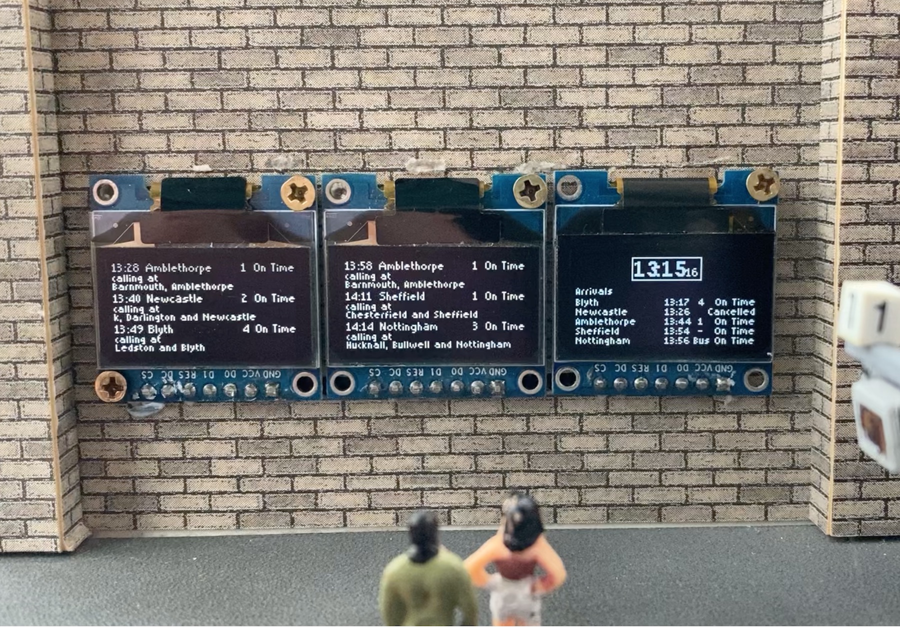
Three modules, two showing departures and one with the clock and arrivals
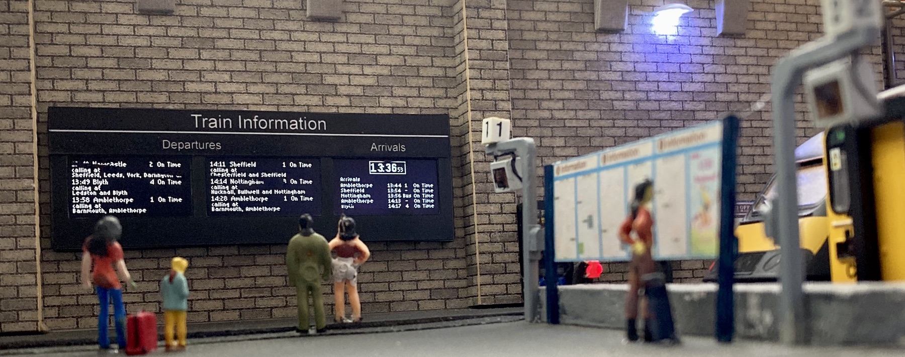
With that big merge of our code, the sketch is now complete. It now generates a station passenger information display, showing the time along with all the upcoming departures and arrivals and even includes an occasional delay, cancellation or dreaded bus replacement train service.
Modelling the Display
The SSD1306 OLED Display Modules are electronic components and look like them. Adding them to a model railway as they are will not look realistic. Some modelling is required to hide the electronics and connectors. This is how I went about adding them to my OO scale railway.
To save space I switched from a Nano to a Pro Mini. This along with the display modules were powered from my DCC track bus via a bridge rectifier and a LM2596 Adjustable Power Supply Module set to 5V.
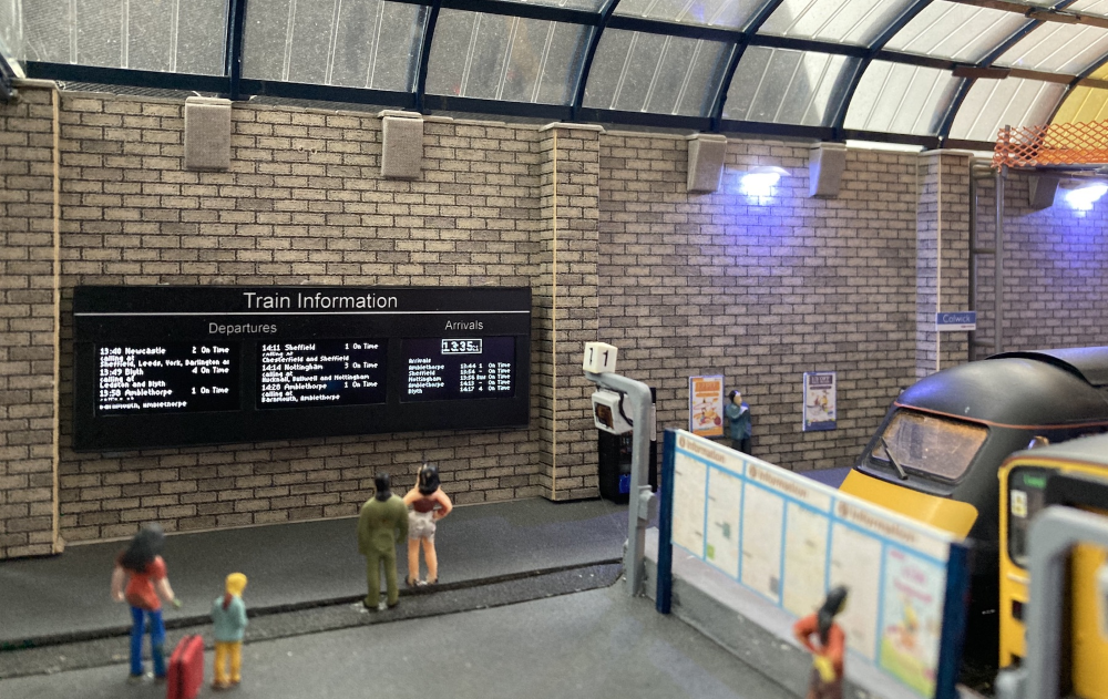
I mounted them on the wall of my terminus station, Colwick. The wall is made of 10mm foam board. This meant only the modules would be visible. The Pro Mini and connections to it are hidden behind the wall.
I soldered female header connectors to the top of a stripboard for the display modules to plug into. I added another two female header connectors to the bottom of the stripboard for a Pro Mini. Tracks in the strip board were cut and link wires soldered in place to create the required links between the Pro Mini pins and the modules. The only other connection to the strip board was a connector for the 5V+GND power supply.
I cut a slot in the foam board wall, just large enough to fit the female header connectors through. On the scenic side of the wall the modules were plugged into the header connectors and screwed to the wall.
To frame the screens I cut a housing out of thin (0.38mm) black Plasticard (styrene) with 13mm high by 25mm holes for each screen. I blu-tacked it over the 3 modules.
The SSD1306 OLED Display Modules are asymmetric. There is 10mm of PCB below the screen with only 6mm above it. The 10mm bellow the screen makes the housing look bulky and it is better to hide this. I achieved this by mounting my screens upside down, so the bulk was above the screen and the 10mm strip along the top now hosts a “Train Information” sign.
This required one final tweak to the code. The Hobby Components library contains Flip functions which enable the display to be flipped on the vertical or the horizontal axis. When mounting the screens upside down the display needs to be flipped on both axis. I added the Flip functions to setup() immediately following their Reset.
/* Reset and flip the display */
HCuOLED1.Reset();
HCuOLED1.Flip_V();
HCuOLED1.Flip_H();

HCuOLED2.Reset();
HCuOLED2.Flip_V();
HCuOLED2.Flip_H();

HCuOLED3.Reset();
HCuOLED3.Flip_V();
HCuOLED3.Flip_H();
The final code for you to upload using the Arduino IDE is available for download on Github here.
I hope you have enjoyed this series and it has inspired you to have a go at making an information display for your own railway.
Hobby Components would like to extend HUGE THANKS to Chris for creating the Model Railway Series. We appreciate all the effort you’ve put in to creating what turned out to be a fantastic series of posts.
Files relevant to this series
1 https://github.com/SharpSharp/ModelRailwayPID/blob/main/HCuOLED_Model_Railway_Departures_Display.ino
2 https://github.com/SharpSharp/ModelRailwayPID/blob/main/HCuOLED_Model_Railway_Clock_Display.ino
4 https://github.com/SharpSharp/ModelRailwayPID/blob/main/HCuOLED_Model_Railway_Arrivals_Display.ino
Library:
https://github.com/HobbyComponents/HCuOLEDhttp://forum.hobbycomponents.com/viewto … =58&t=1817
OR
https://forum.hobbycomponents.com/viewtopic.php?f=58&t=1817
A Note on Electronics
Development of the code for this project was completed using a Nano.
However, the final installation was completed using a Pro Mini.
The Uno would also be suitable, but obviously has a bigger footprint so use of this will be determined by your chosen installation area.
The OLED used was a white backlit module, however, Hobby Components also sell a blue backlit OLED which would also work well.


Chris, thank you so much for this and your other series of blogposts on how you accomplished this absolutely fantastic addition to your station. As well as being so gracious to share your code, I have also found these really useful for me to understand your process on how you built up this project.
Many, many thanks.
Question… which form factor are you using for the modeling? Is that N. TT or H0?
Im asking bc if I buy one of these displays, I want to make sure they are in the right size