


Items you will need:
Arduino development board such as this one
What does it do?
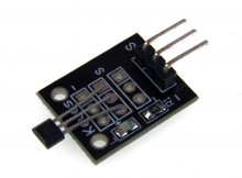
The sensor has two outputs, an analogue output that is dependent on the strength of the magnetic field, and a digital output that will go high if the field strength goes above a threshold level set by the on-board potentiometer. The sensor has two outputs, an analogue output that is dependent on the strength of the magnetic field, and a digital output that will go high if the field strength goes above a threshold level set by the on-board pontentiometer. This example program reads the status of both sensor outputs and outputs the result to the UART.
Pinout:
PIN 1: ANALOGUE OUT
PIN 2: GND
PIN 3: +5V
PIN 4: DIGITAL OUT
Code:
[cpp]
/* FILE: ARD_Keys_Hall_Effect_sensor_With_Analogue_Out_Example
DATE: 06/06/13
VERSION: 0.1
You may copy, alter and reuse this code in any way you like, but please leave reference to HobbyComponents.com in your comments if you redistribute this code. This software may not be used directly for the purpose of selling products that directly compete with Hobby Components Ltd’s own range of products.
THIS SOFTWARE IS PROVIDED "AS IS". HOBBY COMPONENTS MAKES NO WARRANTIES, WHETHER
EXPRESS, IMPLIED OR STATUTORY, INCLUDING, BUT NOT LIMITED TO, IMPLIED WARRANTIES OF
MERCHANTABILITY AND FITNESS FOR A PARTICULAR PURPOSE, ACCURACY OR LACK OF NEGLIGENCE.
HOBBY COMPONENTS SHALL NOT, IN ANY CIRCUMSTANCES, BE LIABLE FOR ANY DAMAGES,
INCLUDING, BUT NOT LIMITED TO, SPECIAL, INCIDENTAL OR CONSEQUENTIAL DAMAGES FOR ANY
REASON WHATSOEVER.
*/
/* Select the input pin for the sensors analogue output. */
#define HALL_SENSOR_ANA A0
/* Select the input pin for the sensors digital output. */
#define HALL_SENSOR_DIO 2
/* Initialise serial and DIO */
void setup()
{
/* Setup the serial port for displaying the status of the sensor */
Serial.begin(9600);
/* Configure the DIO pin the sensors digital output will be connected to */
pinMode(HALL_SENSOR, INPUT);
}
/* Main program loop */
void loop()
{
/* Read the sensors analogue output and send it to the serial port */
Serial.print("Sensor Value: ");
Serial.print(analogRead(HALL_SENSOR_ANA));
/* Read the status of the sensors digital output and if it is high
then send an alert to the UART */
if (digitalRead(HALL_SENSOR_DIO))
{
Serial.println(" MAGNET DETECTED!");
}else
{
Serial.println();
}
}
[/cpp]


There seems to be something wrong with this tutorial. Not minding the fact that the first chapter is repeating, but I do miss some example schematics on how to connect the sensor. Besides, the pinout in this tutorial is different from the actual product description
Thanks for pointing this out. We’re currently revamping the content we have for our range of small sensors as we plan to release a large sensor kit bundle for Christmas. Well get this post corrected and updated with more content soon.