


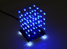
LED light cubes are a hugely popular and fun project and with the help of the Hobby Components kit you will have all the parts to build your very own. Building on the popular 8x8x8 cube kit (HCKITS0022), we decided to create a through-hole version for those of you who are better suited to this kind of soldering. The kits we sell include all the necessary components to build the driver base board and 64 3mm LEDs to build the 4 x 4 x 4 cube. The kit is offered in several colours.
Demonstration Video
Some familiarity with soldering is required to construct the kit.
So, let’s get started! The guide is split into two parts, the first covers creation of the base board, and the second covers the LED cube creation.
The first thing you need to do is check that all the components are enclosed in your kit. If you’ve purchased components elsewhere, be sure to check you’ve ordered the correct values for each component.
Contents
- 4 x 4 x 4 Cube Kit PCB
- 3 x 100nF Ceramic Capacitors
- 2 x 20pF Ceramic Capacitors
- 1 x 5 Pin Connector
- 4 x 5mm White LEDs
- 1 x Pin Header Strip
- 1 x 10K Resistor
- 16 x 100R or 150R Resistors
- 4 x 220 ohm Resistors
- 1 x Tact Switch
- 1 x ULN2803 8-Channel Darlington Driver
- 1 x ATMega328-PU
- 1 x 16MHz Crystal
- 64 x 3mm LEDs (Available in Blue, Green, Red and White)
- Plus: A USB to serial interface cable that can be used to power and reprogram the completed cube*.
*Please see the diagram at the bottom of this guide for how to connect the cable to your cube.
Required Tools
In order to built the cube, you will need a few tools:
- Soldering Iron (Ideally with a fine tip)
- Solder
Recommended Tools
- A piece of perspex or plywood which will be used as a jig for soldering the LEDs that make up the cube
- 3mm drill bit and drill
- A pair of small long nose pliers
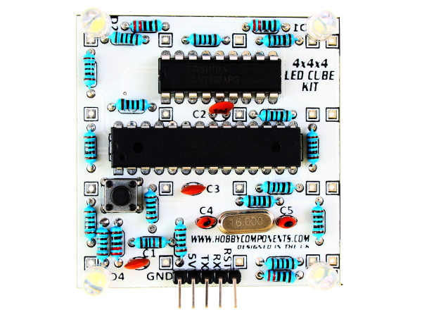
Part One – Building your LED Cube: PCB

Soldering tip: When soldering components to a circuit board it is always best to start with the smallest components first. This helps keep the board flat and stops access to pads from being restricted by larger components. The first step is to start by soldering the resistors and capacitors. In your kit these will be marked appropriately. The orientation of most of the components doesn’t matter. We will point out any components where the orientation does matter. In these cases it is important to make sure you have them inserted correctly.
Components
Resistors
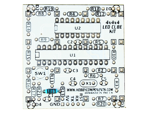
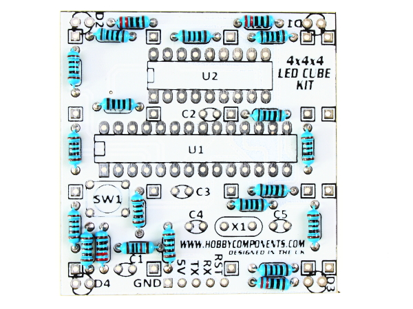
Locate the following pads on the PCB and solder the appropriate resistors in place.
Pad R1 – Resistor Value: 10K (BROWN, BLACK, BLACK, RED)
Pads R18, R19, R20 and R21 – Resistor Value: 220 ohm (RED, RED, BLACK, BLACK)

Pads R2, R3, R4, R5, R6, R7, R8, R9, R10, R11, R12, R13, R14, R15, R16 and R17 – Resistor Value: 100 ohm (BROWN, BLACK, BLACK, BLACK)
Note: Your kit may be shipped with 150 Ohm resistors instead (BROWN, GREEN, BLACK, BLACK, BROWN).
Crystal
Locate the X1 pad on the PCB and solder the crystal in place.
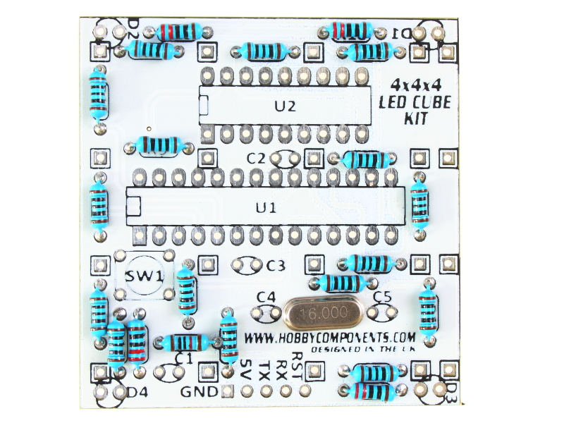
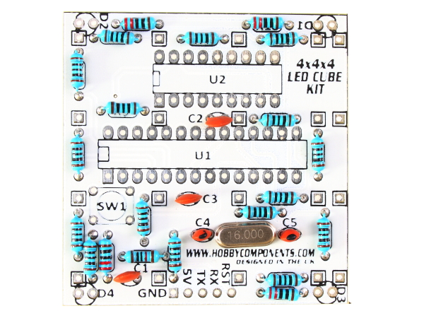
Capacitors
Locate the following pads on the PCB and solder the appropriate capacitors in place.
Pads C4 and C5 – Capacitor Value: 20pF
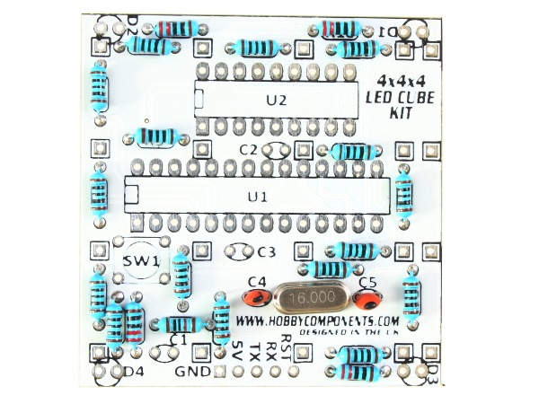
Pads C1, C2 and C3 – Capacitor Value: 100nF
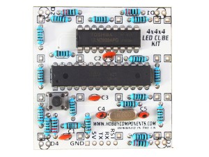
Tact Switch
Locate the following pads on the PCB and solder the switch in place. Note that the switch is a tight fit, but it does push through and sit correctly on the PCB. Note that the orientation of the switch is important – the legs of the switch should be on the left and right hand sides of the components as in the picture below.
Pad SW1 – 4 pin Tact Switch

ICs
Locate the following pads on the PCB and solder the appropriate IC in place. Note that the orientation of the IC’s is important – at one end of each IC you will notice a semi circle cut into the case. When the IC’s are inserted into the board these should be on the left as in the picture below.
Pad U1 – ATMega328-P IC
Pad U2 – ULN IC
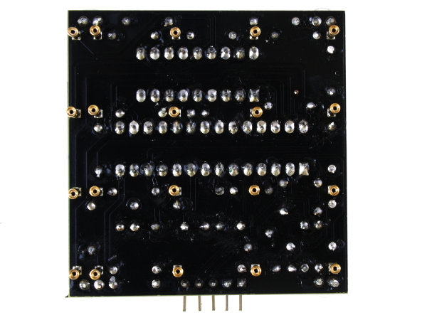
Edit: If you have a version V1.1 PCB (marked V1.1 in low right hand corner) you can skip this next step and move on to the connector…
On the opposite side of the board (black side) use some solder to bridge pins 8 and 9 of IC U2. Reference the image below for the correct pins.

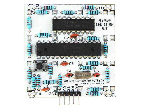
Connector
Locate the five holes shown in the image below on the lower edge of the PCB and solder the right-angled header pins in place. You can solder the connector on the top or bottom side of the board. It’s up to you!
5mm LEDs (Feet)
Locate the relevant pads and solder each of the four 5mm LEDs in place. Note that the orientation of the LED’s is important – the short leg of the LED (called the cathode) should be oriented to the outside of the PCB.
Pads D1, D2, D3 and D4 – 5mm LEDs
LEDÂ Sockets
The LED connectors are each stripped from the enclosed male to female header strip. Carefully snap off each pin and solder to the black side of the PCB as shown below. There are a total of 20. Note that whilst creating our demonstration cube, we stripped off the black plastic from all headers (by lightly squeezing pliers around the plastic until it came away), this isn’t a requirement, it just gives a slightly better look to the finished PCB.
So, you’ve managed to complete all the electronics – Now time to move on to the cube part of the guide.
Part Two – Building your LED Cube: the Cube
After soldering LEDs for the 4x4x4 LED (all 64Â of them!), this one was a doddle! 🙂
To build your LED cube you will need to solder the 64 LEDs supplied in your kit in to four sets of 4 x 4 grids. This will take a little time and so it is important that you understand how to construct these grids before starting.
Whilst with a little care you can construct the grids by hand, it is recommend that you first construct yourself a jig/template as this will allow you to construct the grids quicker and with more accuracy. To do this you will need a piece of perspex, plywood, or any stiff material you can drill holes into measuring at least 5cm x 5cm (in this example we just used a piece of thick cardboard). You will need to drill a set of 3mm holes arranged in a 4×4 grid. The centre of each hole can be marked easily by placing the PCB on top of your jig material and using a fine pen/pencil, or if using cardboard, pushing a pin through. The holes will then all be exactly where needed to create the jig.
Before you start…
Tip 1: Before you start soldering your LEDs together we strongly recommend testing each LED first. You can do this by using your newly built PCB as an LED tester! Simply power the PCB up by connecting the supplied USB cable. Connect the RED cable to the pin marked 5V on the PCB, and the black cable to the pin marked GND. No need to connect the green and white cables, they are just for if you want to reprogram your cube. Next check each LED by inserting it into the two sockets shown in the image below.
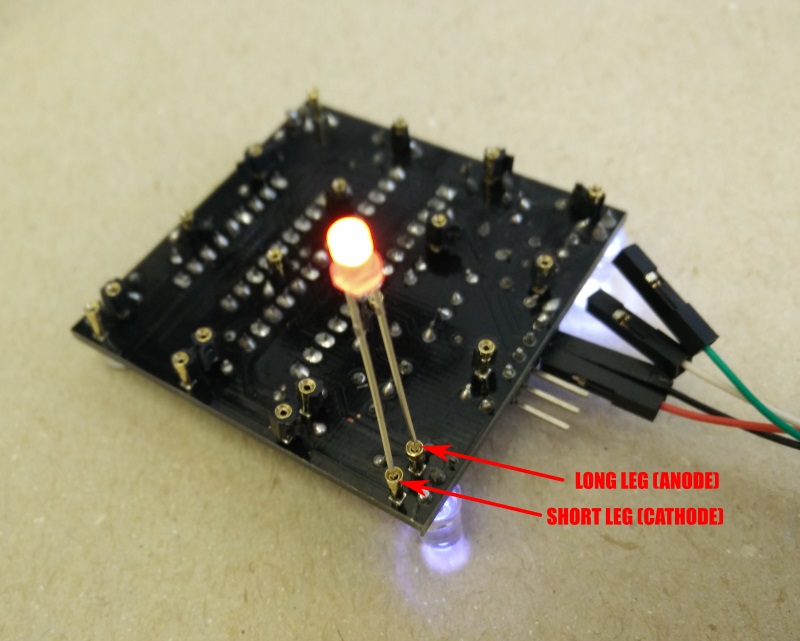
Make sure to connect the LED to the two sockets shown in the image and with the shorter leg of the LED inserted into the outer socket. With the PCB powered the LED should randomly turn on and off as the cube runs through its demo.
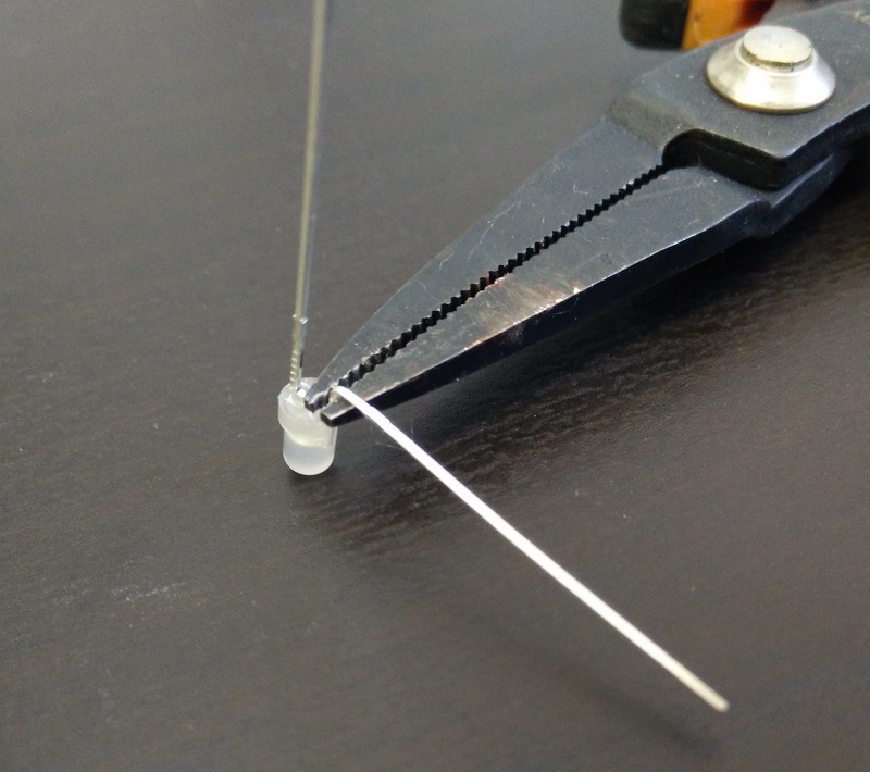
Tip 2: When bending the legs of the LEDs we recommend using a pair of long nose pliers. This will help to avoid applying mechanical stress to the base of the LEDs when bending their legs.
Don’t worry if any of your LEDs don’t work or you make a mistake – we provide extra LEDs in the kit to help cover for any problems.
Step One:
 Â
 
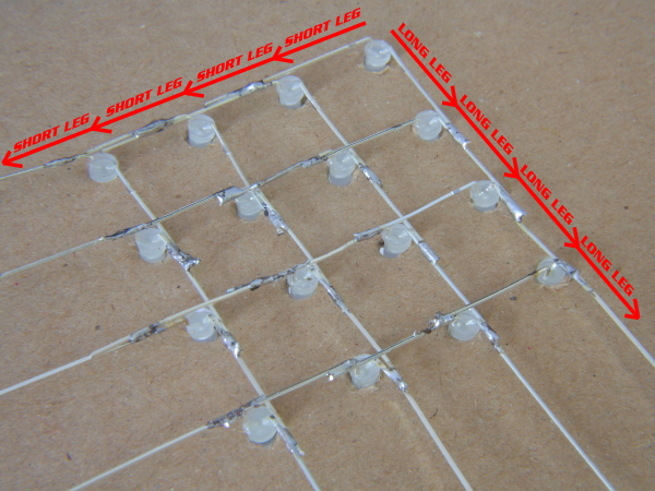
Insert one row of 4 LEDs into your template as shown in the image. Note the orientation of the LED legs with the short legs at the top and the long legs at the bottom. Carefully bend each long leg at a 90 degree angle at the base of the LED so that it points down.
Then carefully bend the short legs by 90 degrees near the base of the LED so that each short leg is touching the short leg of the LED to its left. Note that when bending the short leg, bend it a couple of millimetres higher than the long leg so that it can pass over the long leg of the LED to the left without touching it (see above left diagram).
Make sure these legs to not touch the longer legs of each LED and then apply a small amount of solder to hold them in place.
Step Two:
Repeat step 1 for the other 3 rows. The result should look like the image above with each short leg soldered to the short leg of the LED directly to its left and no short legs should touch a long leg.
Step Three:
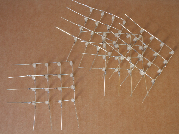
You have now completed one 4 x 4 grid of LED’s. Carefully remove this grid from your template and set it aside. Now repeat steps 1 to 3 to create 3 more identical grids.
Step Four:
 Â
 
Your cube grids are now constructed. All the LEDs of each grid should be pointing in the same direction. Now insert each grid into the controller board. Please make sure you disconnect the controller board from your computer before proceeding. Be careful when inserting the legs of the LED’s into the sockets. They are a snug fit but don’t apply too much force otherwise you may bend the leg or break the socket. You will find it easier to insert the legs using a pair of long nose pliers.
Step Five:

Solder the remaining unconnected short legs of each of your 4×4 grids to the short legs of the grid directly to the right. Start with the top row of legs and work your way down. Before soldering make sure each 4×4 grid is evenly spaced so that the entire cube is square.

Repeat for each layer.
Step Six:

The final step is to connect the short legs of each horizontal 4×4 grid to the 4 additional row driver pins on the edge of the controller board. Reference the red lines in the above image for the order. Each of the 4 controller pins should be connected to one of the horizontal rows with a piece of wire. If the wire you are using isn’t insulated then you will need to make sure that it is slightly bowed out so that it doesn’t touch any of the LEDs it runs past.
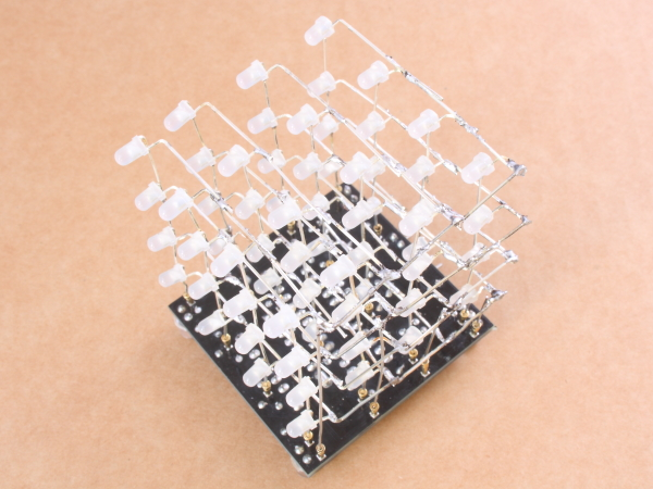
At this stage the cube is complete! If you built one, well done! If you are thinking about building one, you now know how easy it is. Pop on over to Hobby Components and order your kit to get started. The order codes are HCKITS0041, HCKITS0042, HCKITS0043 and HCKITS0044.
Powering your cube with the supplied serial USB cable:
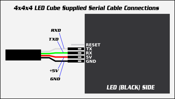
Supplied with the kit is a serial USB cable. To apply power to your cube connect the cable as shown in the above diagram.
The contents of this guide are copyright Hobby Components Ltd and may not be copied, reproduced, or reused elsewhere without permission.


In the 4x4x4 cube when I solder the capacitors, I found an error between the position C1 e C2 20 pfarad capacitors and the immage where the position is C5 and C6 . I am waiting for your answer in my email address. Thank you very much.
Hi Pier, the images are correct so it is C4 and C5 for the 20pF capacitors. The description has now been updated.
For experts in arduino no problem, but for beginners it is a problem….
Thank you for your replay.
Just finished this over a weekend, The pins were little tricky to solder around the large LEDs, might be easier to do those afterwards. I used a cardboard jig which started to wear out after the third grid, but it did work. I’m really pleased with the end result, the kit is a bit of a bargain.
Im on my second one and like you i agree, put the feet led in last. Dont try push them in so they are flat, have them leaning at an angle outward. This spreads the light better. I did not get edge power connector in this kit but i just soldered wires direct to board. I added a longer wire too so i can have it on display on the shelf. The supplied lead is a bit short and too heavy for the kit. Second time round the build is going well. Another note in this kit i have had no LED failiures but on red on had 6 dead led. Maybe blues are tested better before dis[patch to supplier.
Before you solder anything grab a sewing needle and mark out the led jig by pushing a thin needle through circuit board and marking the cardboard. I use the box supplied with kit. After that gently poke a small hole with a sharpened pencil into the pin holes you have in the box.
Great kit thanks.
I was wondering mine is working fine though the LEDs arent coming on fully, instead it looks like they’re blinking really fast.
Compared to the video where they appeared to come one smooth.
Any ideas?
The LEDs are pulsed but so fast you shouldn’t be able to tell so if you can see them flickering then there is defiantly something wrong.
If you’re powering the cube from something like a phone charger, try plugging it into the USB power of a computer to see if it still does it. If it’s still doing it then it’s possibly a bad solder joint somewhere. In particular look for bad solder joints around the crystal (X1), the two capacitors (C4 & C5) and the pins of the large IC (U1).
If you have no luck can you tell me if the cube is cycling though the patterns correctly and at the same speed compared to the cube in the video?
Have it working fine now.
Was wondering if there was a way to set the brightness of the LEDs?
Thanks
That’s great.
The only way to change the brightness on the 4x4x4 cube would be to replace the sixteen 100 Ohm resistors with a larger value I’m afraid. So for example changing them to 200 Ohms would halve the amount of current flowing through them.
Hi
Just finished the 4x4x4 kit and throughly enjoyed it (as fiddly as it is). Powered it up and it works through it’s pre programmed sequence with no real problems, apart from when all 16 leds on the bottom level light it shines much brighter than all the other leds. When the leds light on their own or in small groups they light at the same brightness as the rest of the cube.
I have looked and can’t see any problems. I am no expert on these type of projects but do find building them enjoyable. Hope you can help me try and find what I have done wrong. I have looked and am unable to find any problems eg short circuits or missed soldered joints. Hope you can help me.
Thanks for your time
Rob
I’ve finished mine but only the 4 “feet” LEDs light up. Due to my own ideocy I think I ruined the holes and stripped the pads for R1 (don’t ask!) so I “think” this might be the reason. I figured I might be able to manually wire up the resistor legs to the next components but I don’t know what it should be connected to! Is there a diagram somewhere of what components are connected to what to help me trace the issue? Also, should the cube just light up immediately when plugged in? What is the function of the switch?
As you might have guessed I’m new to electronics and soldering so please go easy!! Thanks in advance.
Simon
R1 is a pullup resistor for the reset pin. I think the nearest pads are the 5V pin on the header and one of the pads of capacitor C1. I’ve added the schematic to our support forum here…
http://forum.hobbycomponents.com/viewtopic.php?f=105&t=1861&p=4459#p4459
…hopefully it will help you figure out how to fix it. The moment the cube is powered up it should start running the demo pattern as seen in the video.
The push button is simply a reset switch which is needed if you plan to re-flash it with your own sketch.
Really enjoyed building this kit! Excellent tutorial!
Is it possible to re-program the cube? How?
You can indeed reprogram it. The kit comes with the Arduino Nano bootloader already flashed into it so it will work fine with the Arduino IDE. Just download the IDE from here: https://www.arduino.cc/en/Main/Software
For the board type (Tools->Board) select ‘Arduino Nano’, for the processor type (Tools->Processor) select ATMega328, and for the COM port (Tools->Port) select the appropriate COM port for the serial cable supplied with the kit. You can then upload sketches as you would with any other Arduino compatible development board. If you are using the supplied serial cable to program it there is one extra step you need to do as the cable doesn’t have the ability to auto reset the the microcontroller which is a part of the normal programming process. To get around this you just need to press the reset button on the underside of the cube when the Arduino IDE finishes compiling your sketch and starts to upload it. You can find more information including links to an Arduino library and the example demo sketch the cube comes pre-flashed with in the first post of our support forum here:
http://forum.hobbycomponents.com/viewtopic.php?f=105&t=1861
Hi, just want to say what a great little project, I did it, and it’s been a while since i did any soldering.
I have 4 LEDs perm on, otherwise it works fine, not sure why the set are on, as i double checked, and cant spot it, but still enjoyable to do.
Which LEDs are they? If the are the 4 white feet they are supposed to be permanently on. If they are part of the cube could you describe which ones they are and I may be able to suggest where to look for the problem.
There is a verticle strip, which is odd – with usb pointing away from you, the lefthand side of the cube, 2nd LED from top on each of the 4 layers is permanently on.
It’s not real massive issue, especially given my first build in a lng while, I am happy with it, and want to progress it, it’s just a niggle 🙂
If I’ve correctly understood which column is causing the problem you may have a solder bridge between pins 19 and 20 on the bigger of the two IC’s.
If you look at the big IC you’ll see a notch at one end. With this IC orientated so that this notch is at the top, pins 19 and 20 are the 5th and 6th pins counting upwards from the bottom right of the IC.
Andrew that all looks OK, as I say I am not to worried, as it’s the first build I have done in a long time, so the fact it works at all is a bonus.
I’m going to get some more LEDs and re-do the cube, as to be honest this one is a mess. but now I the ability to better bend the pins in the right way, using this one as a template.
Thanks for taking time to answer this, it’ much appreciated, and getting me back into electronics and programming.
Hi there. I have just purchased the 4×4 cube and wondered if you could tell where could I purchase some more led’s from, or a part number. The dog got to parcel before me!!!!!!!
Oops! What’s the colour and do you know how many you need?
About 20 green ones. He went to town on the package..
These are the LEDs used in the kit:
http://hobbycomponents.com/opto-electronics/645-3mm-diffused-led-green
We do normally put about 5 extra in the kits so that you have some spare so you may need less then you think. However if you send an email to sales (at) hobbycomponents.com with your order number and reference this blog post we’ll sort it out from there.
I found the cardboard jig really handy, I noticed some people mentioned that it was starting to ware out by the third grid, so I covered my jig with electrical tape which worked a treat, even once the fourth was done, it was still in great shape, might keep hold of it if I decide to make another 😀
Hello, Please could you confirm/clarify that the white lead is Rx and the Green is Tx? I do not seem to be able to connect to the com port, yet when I use another non-cube kit nano with a different lead I can. Is pressing the reset button timing time critical?
Many thanks.
William.
If you have the updated V1.1 cube (it should say V1.1 on the PCB) the screen print has been updated for the serial port with Tx and Rx labeling swapped around. We’ll get the diagram updated in this post to match it. So:
Connect the white (RxD) cable to the pin labeled Tx on the cube.
Connect the green (TxD) cable to the pin labeled Rx on the cube.
Timing of the reset button is a little critical, you need to press it within one to two seconds of the Arduino IDE saying it is attempting to upload the sketch.
Just arrived in post. A note included in package for panikers like me, saying instructions are online. I opened the package and was omg hoiw can I make this without instruction. PS this will definitely not be my last purchase. The website and products are amazing.
Quick tips. Check each led before soldering. I used a |UT30B multimeter and the test voltage was perfect for lighting led. Test again after you solder each 4×4 grid.
plug device into usb point after completing circuit board population. if you put feet led in backwards they wont light.
use the flux!
dont expect your cube to be perfect unless you do ocd on the bending and jig. im happy with a cubish.
Built the blue 4x4x4 led cube today and everything went perfect. was missing the power edge connector. Last kit was missing the single strand wire. O well no prob as have soldered a longer usb lead to blue one and had spare wire for red one. I definetly reccomned making a second one if you can learn from your mistakes as they look quite stunning on the side. My next one will be the 8x8x8 cube, i just hope i dont mess up the board. Be much nicer if it had through hole components as thats what im good at. Surface mount is going to be tricky.
search on youtube for tangobaldy 4x4x4 in a couple of days to see the red one and blue side by side. good demo of how they look if you make them wrong and right.
Hi Dale,
Sorry about the missing parts, not sure why they weren’t in your kits but if you still need them just email sales [at] hobby components dot com.
With regards an 8x8x8 cube we are right now putting the finishing touches to our own kit. Like the 4x4x4 kit this will be a standalone cube and will only have through-hole components so will be much easier to build. We’re hoping to have it on sale within the next week or two. The forum post is still under construction but you can get more information from it:
http://forum.hobbycomponents.com/viewtopic.php?f=105&t=1969
awesome can you email me when its ready. I sure will be buying a few kits for christmas present. Im ok with the odd bits missing. Im sure it a one off. Not worth the postage really. I put link to youtube video i made of the red and blue kit. Its good to see how a beginner can improve after making one. We still like the red on with all the bodge wires to get a few more leds lit. The kits are great fun to make.
at https://youtu.be/ojCqOIu2Als
youtube link if it works
Will do. Like the video, I don’t know what you used to record it but it seems to have very good low light capabilities. I’ve been looking at the video for your red cube but for the life of me I can’t figure out what could cause it to behave like that.
Hi Andrew. I used a Canon Legria Mini in its lowest data rate recording. It can do awesome 1080p but it takes hours to uploads as i barely get 1.5mbps up.
the red one has patch wires as i seem to have killed some of the connections. Whats styrange is I replaced the top right led and it flashes for about 10 seconds then dies. I obviously destroyed something. Im ordering a couple more for friends and will attach 2 meter usb leads that i make myself. Not got into programming the cube as it looks good out of the box. When I get tyhe big 8x8x8 through hole ones I will hook them up to pc if possible. Kinda hoping a simple pc interface is available rather than arduino. thanks for watching the video. Its quit hard to get close without video saturation.
Hi, just finished helping my son do this – he did an amazing job. I say helping (I held a few components together whilst he soldered!) .
Just a quick question – where / how we set about programing the cube with his own sequence etc?
To reprogram it you’ll need to have some familiarity with the Arduino development environment. To point you in the right direction take a look at the FAQ in the first post on our support forum here:
http://forum.hobbycomponents.com/viewtopic.php?f=105&t=1861
It assumes you have some familiarity with programming Arduinos but if you get stuck just let me know.
fantastic model and well priced.
Good results when you take time.
Just doing my 3rd
Excellent support
I’ve just finished building mine. The soldering on it is atrocious, and I was sure that it would never work due to one of the copper pads coming off – but it does work, and it looks amazing.
I mean, it looks crap, because I can’t solder for the life of me, but it works, and that’s the important thing.
Amazing kit – I’d not buy it again – but I look forward to buying the next one – whatever that might be.
When I power it up I get one column illuminate brightly/normally, it then begins the demo pattern – but all the LED’s are extremely dim (can barely be seen even in total darkness).
The only anomolie I can spot is that IC U2 supplied has 16 pins, whereas the PCB “expects” an 18 pin chip. I have installed it with the chip to the far left, leaving the far two RH pins unused.
It definitely sounds like you have the wrong IC. I can’t locate your order in our system from your name. Could you email sales at hobby components dot com referencing this blog post and try and resolve the problem from there.
Update – it was the wrong IC, replacement kit sent out by first class post without any fuss. New board built & working perfectly!
Great kit & great customer service…next stop 8x8x8!!
In step five with the bending of the LED legs to the right, are the rightmost legs supposed to be snipped off? It’s not easy to tell from the pictures?
It’s optional, it will look slightly neater by doing this but just make sure you leave enough overlap onto the next LED so that you can solder on to it.
I just realised that on my board, the TX and RX are the other way round than as shown in the “attach the cable” image, see: http://imgur.com/ZAL7A0W
Is white>RX and green>TX still correct and they’re just transposed?
The diagram needs updating. With the latest version of the cube PCB (V1.1 which is the one you should have) the labeling for the Tx and Rx pins have been swapped around. The pins themselves have not changed. So you should still connect the the cable in the same order as shown in the diagram.
Just built the kit, no problems with board (Although I agree solder the feet on after). Looks great. Soldering the LEDs is pretty fiddly. I can imagine the 8×8 cu e is a real trial…
Hi Colin,
That was quick considering you only purchased it from us yesterday.
The 8x8x8 cube is of course a much bigger project but as with the 4x4x4 cube it’s wise to create a jig out of cardboard or wood etc. It’s then just a similar process to making a 4×4 grid but bigger.
With the 4x4x4 cube, if your confident you can get away without making a jig but with the larger cube even if you’re experienced at soldering I would not recommend constructing one without a jig.
Excellent little project – I was fortunate enough to have no problems whatsoever, it just worked.
im glad i read these comments and checked all my leds before I started building, would have been pretty annoyed to build it with the 11 dead red leds inside the cube, I can probably find the 5 I need in my garage to finish it, but it does seem a shame to spoil such a nice kit with leds with such a high fail rate, makes me worry about how long they will last,pcb looks very good quality, and quick delivery.
Hi Mark,
We’re going to run through our current stock of RED LED’s to see if we can pin down what exactly the issue is. I’ve added an update to the guide to include a section on testing the LEDs before construction and a tip on avoiding mechanical stress when bending the legs. We’ll also look into increasing the number of spare LEDs within the kits to cover for any potential problems.
If you send an email to sales at hobbycomponents dot com we’ll see what we can to resolve your current problem.
Hey,
Wondering if you could help me – just finished my cube! Took me the better part of today Soldering the led’s together is really fiddly got there in the end though. For the most part it seems to work buy for some reason all of the leds on the bottom and second row work. Not sure why the 1st and third row not working. Doesn’t seem to be anything loose soldering wise – any ideas? Thanks for your help!
There’s nothing particularly special about those two layers and the fact that the other to layers are working helps rule out a lot of possibilities so hopefully its something minor.
By not working do you mean none of the LEDs are not lighting or that they are not lighting in the expected pattern? Also is it running the default demo that’s pre-loaded into the cube or have you reprogrammed it?
Hi there,
thoroughly enjoyed making this as a complete noob! am now pondering creating my own sketches and have followed instructions. however the arduino IDE doesn’t seem to be able to detect the board. checked system properties and it says “The drivers for this device are not installed. (Code 28)
There is no driver selected for the device information set or element.
To find a driver for this device, click Update Driver.” where would I find this driver?
Glad to hear that you enjoyed building the kit. The serial cable supplied with the kit is actually this one:
http://forum.hobbycomponents.com/viewtopic.php?f=79&t=1815
You can find more information including a link to drivers in the first post. The Arduino library and sketches for the cube can be downloaded from this forum thread:
http://forum.hobbycomponents.com/viewtopic.php?f=58&t=1860
Remember to select ‘Nano’ as the board type in the Arduino IDE.
Ah great, thanks for that.
Hi
I’ve just received the kit and I’m looking forward to building it. I’m impressed with the value for money and the support it has.
However, I’ve been a bit confused by the circuit board. All reference to this in the build instructions show the component side as white and the reverse as black (including a picture of a v1.1 board from a contributor). Mine is a v1.1 board but the colours are reversed – what I take to be the component side with the text on it is the black side and references to the “black” side seem to mean my plain White side!
I’m sorry if this sounds a bit nerdy but it’s confusing. I’ve not done much of this sort of construction and it has caused much head-scratching and wondering whether I’m interpreting the instructions correctly.
Perhaps a clear statement of these changes, along with the Rx / Tx issue (which is still incorrect on my board), should be placed at the top of the instructions.
Is there some reason for this change? I would have thought that having the white side uppermost on the completed project might cause undesirable reflections from the LED’s.
Finally, should it be OK to use chip holders for the 2 IC’s?
Regards
>I’ve been a bit confused by the circuit board….
Sorry for the confusion. We use an external PCB manufacturer to make the PCBs in our kits. Currently shipped PCB are reversed simply because the manufacturer made a mistake when applying the silkscreen to the latest batch. After building one up we didn’t find any issues caused by the silk screen being reversed. At one point we where offering a choice of PCB but we are currently sold out of the older version.
>Perhaps a clear statement of these changes, along with the Rx / Tx issue (which
>is still incorrect on my board),
Thanks for the suggestion. A comment has been added to the start of the build guide and the serial cable diagram has now been updated.
> I would have thought that having the white side uppermost on the completed
> project might cause undesirable reflections from the LED’s.
Actually there is not much difference as the black PCB is glossy and causes reflections anyway. In fact, personally I think it looks better with the white base.
>Finally, should it be OK to use chip holders for the 2 IC’s?
Yes it will work fine. With standard IC holders the ICs shouldn’t protrude above the height of the 5mm LED feet.
I have just constructed the cube. I’m fairly new to electronics.
None of the cube’s LEDs are lighting up, but my four white LED’s on the driver board are. LED’s were also working when I tested them, showing that power is being supplied.
I still have legs pointing out at the back of the cube. It didn’t say to either cut them or connect them down a layer on this guide… Can I have some help troubleshooting, please?
Answering my own question…
Realised that my image was flipped from that of the guide.
Turns out I had ALL the polarities wrong on my cube.
A bit of unsoldering and rebending, and I’ve got it working fully now.
DON’T DO WHAT I DID! haha.
I’ve just finished mine and my lad loves it. The wife asked me whats it for, but I had fun building it.
Thanks alot
Just completed the kit. It’s quite fiddly, but a good test of soldering skills. If you are 40+ like me, you may wish to invest in a good magnifier! Take your time, check the solder joints as you go and its worth investing the time. Good job on the kit guys.
Hello,
Im new here and to the whole arduino/electronics thing. Can someone please explain how exactly this connects to the arduino ?
It doesn’t – the cube will work by itself. All you need to do is connect power to it via the supplied cable.
It does however have it’s own built-in microcontroller with the Arduino bootloader. So if you want to create your own patterns you can program it directly from the Arduino IDE.
Hi everyone,
I’m kind of new at this hobby and I can’t tell you how pleased I am with this product and the good folks at HC.
It assembled and runs just like it’s supposed to, first time, no adjustments needed. Thanks. On to the 8X8X8 next 🙂
Built it and works like a charm (almost) first time around! I am new to electronic hobby kits and only had some soldering experience in school clubs (wayy back). This kit was great to get reintroduced, and I’ll be coming back for more!
I have a question – sometimes the light display gets stuck on top plane of cube, all led lit in that plane. Other times it keeps going on and on, till it randomly gets stuck again – always on top plane. Have turn it off and on to get it going again. Is this some safety feature in the circut? Nothing ‘seems’ loose.. How could I debug this pls?
Thanks
Glad to hear you enjoyed the kit. If the animation randomly stops then this is a sign that the microcontroller is locking up for some reason. Obviously it shouldn’t be doing this so something must be causing it to crash. The most likeliest cause is a dry solder joint somewhere so I would first double check all the soldering on the PCB – I doubt it’s anyhtign to do with the cube itself. Especially check the pads for the crystal (X1), the 22pF capacitors C4 & C5 and the GND pin on the microcontroller (pins 8 & 22).
Just finished building my cube, but I have 1 column of leds that never light. All else seems to behave OK, with the various patterns and sequences. The ones that don’t light are the column with the pin nearest the gnd pin. I put a voltmeter on several columns and the voltage bobbles about on all other pins, but this column stays resolutely at 0V. Any ideas?
Hi Iain,
Assuming I correctly understand which column you’re referring to the problem is most likely to be a bad solder joint at one of the following places….
1) The solder joint to the first LED in that column.
2) The pad for the socket that column is inserted to.
3) The pads of resistor R13
4) Pin 6 of IC U1 (the 28 pin IC) – to find pin 6, pin one is in the top left corner of the IC and normally has a small round dot next to it. From pin one just count down that side of the IC until you get to pin 6 and check its soldering.
Exactly right Andrew – I had failed to solder 1 leg of R13 entirely, and even though I had checked the board over I didn’t spot it. All working fine now! Many thanks
Great. Problems are almost always due to a missing/bad solder joint but that’s because it’s easily done.
I built the cube and it works but, randomly, the cycle stops and not always at the same point. Restart from the beginning only by pressing the reset
If your cube is randomly stopping then the most likeliest cause I can think of is a bad solder joint somewhere. If you haven’t already give the solder joints a visual inspection – preferably with a magnifying glass if you have one as cracked solder joints can be hard to spot. Pay particular attention to the pads around the big ic. Other things to check/try:
Check that no components on the cube are getting hot to the touch.
Try lifting the crystal slightly off the board. You can do this by heating one leg of the crystal at a time and gently lifting each side whilst the pad is heated. Don’t use excessive force otherwise you may risk pulling off a pad.
Check the soldering around the two 22pF capacitors. They are quite small and delicate so also check their cases aren’t damaged around the legs.
Finally have you tried powering it from a different USB supply?
I just got this kit a couple of days ago. I haven’t done any electronics since 1984…. I’m 73.
Worked first time.
Brilliant little kit.
Going to look and see what other kits they do.
Bought my kit a few days ago, and it works very well.
Great kit, I might buy another and learn how to program the LED sequences.
Just finished this and enjoyed building it immensely. Didn’t work at first apart from the legs lit up but after some investigation I found a short in my LED assembly though the main problem was one of the IC’s was hanging out of it’s socket (I ordered sockets for IC’s) at one side. Recommended!
Just finished my second cube (blue & green) and very impressed with results especially considering the cost of the kits!
One thing I need to mention, I have seen quite a few comments about the LED’s flickering or the cube randomly locking up and resetting to the beginning. The flickering happened on my blue cube, especially the bottom row, and the locking up & resetting problem happened with my green cube. I am a very experienced electronic engineer and always check all my solder joints as I go along.
Right from the start of the first cube I did think it was strange that no reservoir capacitor is included on the 5v power. It occurred to me that this could cause a problem if your power supply was not very clean. I tried different USB chargers and swapped the cables between the 2 cubes and found that the problems got better/worse with different power setups.
So I got a 100uF electrolytic cap (10v or above but keep it as physically small as possible) placed it on the top/LED side of the board and soldered it across the +5v and GND on the connector – remember to observe polarity!
This has cured all the problems on both cubes and all chargers work perfectly now! Since so many people are experiencing similar problems, I suggest you add a note to the assembly instructions about this and consider adding a capacitor to the next version of the PCB and kit.
Hi Steve, thanks for your feedback, it’s very much appreciated. With regards to the flickering I’m actually only aware of two cases of this issue (excluding yours of course). Unfortunately we’ve never had feedback as to if this was ever resolved or what was the actual cause. USB specification requires the voltage of a USB supply to remain within +/- 5% and as the cube only draws around 15-20mA when it’s running I’m inclined for the moment to make the assumption that the flickering issue is due to an out of spec power supply. If this is the case then I’m a little reluctant to suggest anything other than trying a different USB supply because if the adapter is indeed operating out of spec it could also be over-voting as well as under-volting the cube which of course could ultimately damage it. I’d really really like to get more feedback on this issue to definitively pin down the cause but at the moment my best advice is to try supply with a known good output such as a PC or laptop USB port to see if the problem goes away.
Are the adaptors you are using branded ones? Maybe we can get hold of one ourselves to see if we can replicate the problem.
Hi Andrew, thanks for your reply. The adaptors are both branded Apple chargers that came with Apple devices. I did try a third one on the blue cube before adding the capacitor and it seemed to work fine. I’m sure if you were to run the cubes from a completely clean supply, like a battery, it would be fine, but nobody is going to do this.
I have measured the unloaded voltage of the adapters and they are both within a couple of percent of 5v. It’s just they must be a bit noisy.
Also, I am pretty certain that most people will not want to switch on their laptop or desktop computer to power their cube, much preferring to plug it into an adapter like me.
Thing is, as I mentioned in my first post, I am an experienced professional electronics engineer and putting a reservoir capacitor on the power input of a device running from an external DC supply is considered very important. If nothing else it will ensure that any noise on the supply is filtered out and the cube will work fine no matter what 5v supply it is run from.
>The adaptors are both branded Apple chargers that came with Apple devices.
That’s surprising. We’ll there shouldn’t be any issues with quality. I’ll try to see if I can take a look at how they work and any specs. Maybe they could be switching between charging modes because they don’t know what’s connected, or they simply don’t like something that isn’t an apple device connected to them. It could even be that the cube is drawing too little power from them to work properly. Some switch mode power supplies need a curtain amount of load to work properly and the cube takes a relatively small amount of power. These are just guesses obviously for other possible causes. I think in the future if anyone else reports this problem it will be useful to get the brand of adapter used.
>Also, I am pretty certain that most people will not want to switch on their laptop or desktop
>computer to power their cube
Sorry, I didn’t make that clear, I mean as a debugging exercise.
>Thing is, as I mentioned in my first post, I am an experienced professional electronics engineer
>and putting a reservoir capacitor on the power input of a device running from an external DC
>supply is considered very important. If nothing else it will ensure that any noise on the supply is
>filtered out and the cube will work fine no matter what 5v supply it is run from.
Yes it’s a very helpful suggestion. It’s just we can suggest it as an official fix without knowing what the actual cause of the issue is.
This sounds very similar to my experience. Only difference is the added 10 Ohm resistor.
I’m not getting any blinking when testing LEDs. The feet do light up.
My IC is labeled “ATMEGA328 U” (yea, 328 space U) – is that legit?
I thought I’ll try uploading the sketch just in case, but I get this:
avrdude: stk500_recv(): programmer is not responding
avrdude: stk500_getsync() attempt 1 of 10: not in sync: resp=0xd4
Any ideas?
>My IC is labeled “ATMEGA328 U” (yea, 328 space U) – is that legit?
Yes, the ATmega328U is a minor variant of the PU version. We buy our Atmel chips directly from Microchip so these are definitely genuine parts. We also program the bootloader and demo sketch ourselves so any issues with the chip itself would be picked up at that point.
>I’m not getting any blinking when testing LEDs. The feet do light up.
>I thought I’ll try uploading the sketch just in case, but I get this:
>avrdude: stk500_recv(): programmer is not responding
>avrdude: stk500_getsync() attempt 1 of 10: not in sync: resp=0xd4
By this I’m assuming you are testing the LEDs using the method described in tip 1. As mentioned above the microcontroller comes with the demo sketch pre-installed so if you’re not seeing any blinking LEDs then this would suggest that it is not running for some reason. The fact that the base LEDs are on tells me the cube is at least getting power but there could be a number of reasons why the microcontroller may not be running. I would first suggest checking the following things…
1) With the cube powered up is either IC getting hot to the touch?
2) Can you double check the soldering for all the pins on the microcontroller (labelled U1). Especially pins 7, 8, 9, 10, 2 & 22, but also give the other pins a good check. Also make sure that none of the pins of the IC have bent under the chip rather than going through the pad.
3) Check the pins of the crystal X1 and the two 22p capacitors C4, & C5. Also try lifting the crystal slightly off the board by heating one pin at a time and carefully lifting each side slightly
Hey, thanks for the quick and thoughtful response! I got it working by resoldering the crystal. It didn’t look bad so I’ll never know exactly what the problem there was, but anyway. The project shall continue.
Having built the 8x8x8 during lockdown and found it a walk in the park, I got a red 4x4x4 to build as I thought it would be a cute addition. Firstly I was a little disappointed to have five times as many dud LEDs than I’d had with the big cube, but with that overcome all four grids were tested on completion and found to work. I was somewhat shocked to find that when soldered together I had missing LEDs to begin with and there started the trouble shooting. I eventually got the lower 16 followed by the second 16 to alternate and then stall. I unplugged the fly leads and reconnected one at a time and yes I could get sections of the cube to do as it should, a different area depending on the lead so I figured all areas did work. Reconnecting more than two leads led to incorrect operation and stalling. I rechecked all solder joints still not working. Checked that nothing was hot or smelling no nothing wrong. I’ve tried a usb socket, a usb on my laptop and a usb plug adapter and the only noticeable difference is that now none of the red LEDs come on having plugged it into the laptop, just the corners.
Any ideas or is this a dud?
>Firstly I was a little disappointed to have five times as many dud LEDs
We do put extra LEDs in the kit. I take it you had enough to complete your cube?
>I’ve tried a usb socket, a usb on my laptop and a usb plug adapter
>Any ideas or is this a dud?
Well my first suggestion would have been to try a known good power supply like a computer USB port but that can be ruled out. The next likeliest thing would be the crystal. Can you try lifting it off the board a bit. You can do this by carefully heating one pad of the crystal at a time and lifting it a little.
Ok tried that and now all I get are the four corners , none of the red LESs are coming on. Again I’ve tried different power supplies and pressing the rest but I get no red LEDs.
Any other ideas?
>Ok tried that and now all I get are the four corners
The LEDs on the corners are connected directly to the 5V supply so that at least tells me that the cube is getting power. But does this mean that just before you lifted the crystal something was happening with the red LEDs or was it still completely dead from when you did the original power supply test?
Before the crystal was lifted I was getting one red LED on the edge of the second grid up from the bottom when powered from my laptop USB.
Now when I bought this red one I also got a blue one for my son to build. I have knock that up in exactly the same way as I built the red one to act as a direct comparison. I did leave the crystal further from the board as recommended in mine and other blog conversations. I’ve then plugged the red led cube into this board and it worked first go off of my laptop USB. I therefore don’t think it is something I’ve done in the building of the the cubes. The first board it does seem to genuinely have a major fault seamingly in one of the chips.
Yeah I doubt the problem is anything to do with the LEDs, the problem is most likely that for some reason the microcontroller. If it was running I’d expect to see at least some of the LEDs flash.
I know you’ve checked the soldering and pins but could you give the following points I’ve highlighted in red another check just to be sure:
If it’s ok, I’d like to email you directly as the blog post is not the best place for remote debugging and we can look at an alternative solution to resolving the problem.
All highlighted pins checked and re heated with solder and inspected. Reconnected to known reliable power supply (laptop USB) and still just the four corners are on, nothing else.
Please direct email to resolve this.
HI,
I’ve managed to build this but it seems a couple of LEDs at the top edge dont turn on. I’ve checked them all beforehand and even touching a new LED onto the legs of them fails to yield a result. When looking from the front (connector at the back) its the far right edge, top, middle 2 LEDs that dont turn on.
Thanks for any help.
If only individual LEDs are not working (i.e. not whole columns or entire 4×4 rows) then it must be the individual LEDs themselves that have failed. Being small components they are a little susceptible to mechanical and heat stress. It sounds like they must have gone short circuit which would explain why placing another LED across them wouldn’t work.
You’ll need to unsolder and replace them I’m afraid. Fortunately we do put extra LEDs in the kit so you should have some spare.
Ah, thanks for the reply. Would that also be the case for LEDs that are producing a weak light?
Yes all the LEDs should be the same brightness so if you have an individual LED(s) that are dim it’s either a bad solder joint for that LED, or it’s partially damaged.
Update: replaced the LEDs, they do now indeed light up. I only had 3 spares and a few other ones were malfunctioning So I managed to fix 3 of them. only about 1 or 2 left are still iffy/weak. But looks much better, Next time I’ll bend them much more carefully.
Thank you
Just completed this little kit which I got as a Christmas present.
LED matrix was fiddly but all worked first time – really pleased!
Hi Matt, glad you enjoyed the kit. I guess it couldn’t have taken you very long to build it!
Hi, I’ve just started to build this kit and unfortunately haven’t got all the capacitors required- am missing 3 x 100nF Ceramic Capacitors. Is it possible to get replacements sent to me? I am assuming the other two Capacitors marked ‘22’ are the 20pF ones?
Many thanks in advance!
Sorry about that. The 100nF capacitors are just precautionary and are there to remove any noise on the power supply. So the cube should work fine without them. However if you email sales [at] hobbycomponents.com with your order number we can arrange to have some sent out to you.
Thanks for the quick reply Andrew 🙂 I’ll do that, just to complete it.
It’s good to know I can proceed without them- am now ready to test my LEDs.
Loving it so far and thanks again for the help and advice.
Hi Andrew,
In Step 5 of the above, it is not clear what is used to make the connection across the legs. What do you recommend?
I have an idea for a variation of the leg bending routine I will post in the Kit forum with a picture to support. If you could take a look and comment it would be appreciated.
The short legs of the end column LEDs should be left untrimmed. You can seen them sticking out to the left in the first image of step 4. You can also see them pointing towards you in the first image of step five. Looking at that first image of step five you need to bend each of these legs to the right and solder it to the short leg of the LED to its right. Hope that makes sense.
Will do.
Hi Andrew,
I need help sorting out an issue with my latest cube. At first power up only one layer lit, dimly at that. Went around and double checked solder joints, touched up a few to be sure, checked for bridging, pulled the 328P and checked all pin locations connected with the appropriate resistors and sockets, Checked other pins to make sure they went to the ULN2803 correctly, the caps and the oscillator.
Still no joy. Tried to reprogram the 328P using the Nano with old bootloader by way of my FTDI. wouldn’t take the upload. Replaced the 328P with a spare with the same Nano bootloader setup. The sketch ran all the way through then froze with the top layer fully lit. Strangely it would only run while connected to the power from the FTDI, not from my other 5VDC sources. Tried the original 328 after loading the sketch on it using a spare UNO and it will not run, does a few flickers and freezes.
Could I have a bad or poorly soldered oscillator or capacitor possibly? Strange that it ran through the sketch once with all LEDs working as they should then stopped.
Any suggestions where to start looking next?
That at least confirms that you have a working 328 device. Also the fact that it did at least run though part of the sequence rules out other possibilities including the LED cube itself.
As you suggest, the first thing I would check is the crystal and two 22pF capacitors. Try lifting the crystal off the PCB slightly by carefully heating each pin at a time and lifting one end at a time just in case there is any solder or flux under the crystal causing problems.
If you have a multimeter I’d also check that there is ~5V across pins 1 & 8, 7 & 8, and 20 & 22 of the ATMega328 (U1). I doubt U2 is the issue but you while you’re at it, check there is 5V across pins 1 & 9 of IC U2.
Do the base LEDs light up when you power it from your other power sources?
using Wall wort #1 5.1 vcc-gnd
1-8 = 5.17
7-8 = 5.17
20-22 = 5.17
Base lights only
Wall wort #2 VCC-GND 5.13
1-8 =4.42, 2nd try 5.13
7-8 = 0, 2nd try 5.13
20-22 = 4.66, 2nd try 5.13
Base lights only at first, when I touched ground lead from MM to Pin 8 cube lights started flickering. After second try, base lights only.
ATX power supply to breadboard 5.0 VCC to GND
1-8 = 5.0
7-8 = 5.0
20-22 = 5.0
Base lights plus some random red LEDs in partial patterns
pressed reset button – base light only
FTDI all points 5.0 v
started into the sketch with some cube lights flickering then
base lights only
I’ll check out crystal and caps this evening.
I tried to measure voltage at small caps and when I touched the lead between cap and crystal I got some flickering and random LEDs.
Would it be possible to get pdf file of schematic? The one in the forum is blurry and hard to red pin detail.
The forum does shrink the schematic image a bit so if you right click and download it then open it up in something like paint then you may find it to be more readable.
Thanks for checking. All those voltages look good. Just for reference the base LEDs are directly across the 5V supply so if they were to flicker at any point then that would be a power supply issue.
Pin 8 is just a GND pin but it could point to the problem being power supply related.
OK, well the mystery deepens.
I removed the oscillator and replaced it with a spare, temp’d in with jumper cables.
That didn’t result in any changed so I swapped the IC again after making sure it was uploaded with a current demo sketch and Nano “old bootloader’. It worked! for awhile then it started freezing part way through the demo sketch. Not at any specific pattern, just freezing. I noticed the old cube was running slower so I made sure to load the same sketch on both and have them both running simultaneously to compare them side by side.
In the mean time I tried burning the bootloader to the original 328P and loading the sketch to no avail. I tried burning the bootloader with the UNO board selected. No go. I was able to load the sketch with the holding the shift key down trick but haven’t put that chip back in play yet.
I don’ t have the ability to test the supplied oscillator and have the original IC with it off to the side for now. Everything is running at 250 speed and it seems to be OK for now. I’ll solder in the replacement oscillator if you think that is a good decision. not understanding the other behavior.
Crystals don’t like to be on long tracks or wires so that maybe that’s why it didn’t work.
Again this suggests it could be just a bad solder joint somewhere and it’s just that particular IC is just more tolerant to it.
That is very odd. A microcontroller is clocked at a precise frequency and should definitely not change speed. That again points to something either crystal or noise related such as bad power supply noise or a bad connection.
I know from previous discussions that you’re using some sort of third party Uno shield to do this and there’s something odd about the way it works. Unfortunately as it’s not something we sell I can’t comment about why it didn’t work. The only thing I can say is to not forget that if you flash a sketch via the ICSP interface it overwrites the bootloader so you wont be able to upload a new sketch in the normal way until you put the bootloader back on it. To get both the bootloader and the sketch on the chip at the same time you first have to burn the bootloader via the ICSP interface then upload the sketch in the normal way via the serial COM port.
So am I right in assuming that currently it’s running ok but just going through the patterns faster than it should be?
Hi Andrew,
Sorry, too many things all going on at same time.
With both cubes running at 250 they do run thru the sketch at same speed (it is a beautiful thing to watch :-)) After running through the sketch for awhile the red one freezes up.
They both have a short (1-2 second) delay on power up between the base LEDs lighting and the sketch starting. Bootloader delay maybe?
Sounds like my next task is to solder in the new crystal. The original’s legs are now too short to easily get into place and solder. I’ll do that and see if the stability improves.
Yeah, that will be to bootloader causing the delay. When it boots up it has to wait for a moment to see if you’re wanting to upload a sketch via the serial port before going on to run the sketch that’s been flashed into it.
Hi Andrew,
Soldered in the crystal. Set up a breadboard to burn the 328P chips with Nano Old bootloader and demo sketch. Actually was able to use the original crystal even with the short legs.
Now for the strange part, the cube runs fine using the FTDI VCC and GND pins to supply power. measured 4.93V at FTDI pins and between pins 1 and 8. It will not run on any of the other 5VDC sources that measure slightly higher at 5.05, 5.13 and 5.18 volts. I lights up the first layer and the base LEDs but does not progress thru the sketch. Changing nothing else, plugging back into the FTDI it runs fine.
Ideas?
I tried building a voltage divider to reduce the supply voltage and was able to get it to run for awhile at 4.5V before it started acting up. After tinkering all afternoon and reburning the chip a few times, just to make sure it didn’t get messed up in the process, I’m back to a locked up display at 5.1+ volts and now nothing but flickering using the FTDI at slighter lower supply voltage.
If it’s working fine with the FTDI lead but not with your adapter(s) it could be the adapters are either too noisy, or if they are switch mode adapters such are phone chargers (most are these days) it could be that the cube isn’t drawing enough power from them to work correctly. There is a previous poster (Steve) that had this issue with his adapters and solved it by putting a 100uF capacitor across the 5V supply. Do you have a capacitor around that value?
sure do, I’ll give that a try while using one of the 5V power supplies.
The ATX is less likely to do this I suppose. I do have it supplying several things at once, most notably an infinity cube and a Neopixel strip both controlled by UNO’s. The green cube runs on that same supply. I’ll try that supply without anything else hooked up so the stability of the 5V is eliminated as a consideration.
The 100uF by itself was not effective with the 5V power supply.
I added a 10 Ohm resistor inline on the positive side and the sketch started running. I’ll keep it running and see if once it has warmed up, things change or keep on blinking. Thanks, Todd
After running for awhile it started flickering again. I’ll recheck all my solder joints again. What would you suspect is maybe warming up to cause the good start then flickering later syndrome?
I immediately switched to the ATX PS and the flickering continued, eliminating the wall wort as the source of the noise.
The ATX supply without the cube plugged in is 5.0 V. measuring across the legs of the capacitor with the red cube plugged in it drops to 4.65V.
I swapped the green cube in and it runs OK with voltage bouncing from 4.65 to 4.9V measured across legs of cap and on the right angle pins on the cubes
Thanks for trying the capacitor. 4.65V is getting a bit low. The ATMega328p is specced only to run at 16MHz above 4.5V and so 4.65V is getting quite close to that. There could be power supply transients that could cause it to dip below that which your Multimeter won’t be sensitive to detect. It’s probably not the problem but I still wouldn’t rule out a power supply issue. The problem is that it could still be a number of things and so far we haven’t really managed to rule any of them out..
The comments section of this site is not exactly ideal for remote debugging and as this is starting to run on a bit I would like to take this offline and email you directly. I have your email address so I’ll email you shortly.
Demo patterns were stalling for us, usually with top plane lit permanently after only a couple of seconds, powered by a rechargeable power pack. Ran a bit longer off a 2.4A capable wall wart, but still stuck after a while with top plane lit.
Following the suggestion from another comment, I soldered a capacitor across GND and +5V (i used a 47uF electrolytic) and now it is stable, runs continuously off either power supply. This was with the blue kit.
I would like to encase the cube in resin when complete. Does anyone think this would work. Would there be a problem with heat build up if entirely encased in resin. I think it would look good, and make the whole thing more robust.
An interesting idea. I don’t see a problem as far as heat is concerned as none of the components get hot. The only thing I can think of that could be a potential problem is the resin getting under the crystal and affecting it but probably unlikely to be an issue. Other than that I don’t know if you are using resin intended for potting electronics but you’d want to check that it’s curing temperature doesn’t go above 85oC.
Thank you for your response Andrew. I will let you know when I get around to it. Dave
Hi Andrew,
I did eventually get around to encasing the 4×4 led kit in cast resin, so I get a solid cube. It works really well. Its very robust. When the cube was complete, and working, I made a container 55mm square x 62mm deep. The led cube could be inserted into this upside down. I then poured the two part casting resin in so that it came exactly level with the pcb. This left the pcb components, the led feet, and the connector free. twenty four hours later the resin had set, and I could cut away the home made container. I had made this from thin modelling sheet gaffer taped together. I am very pleased with it
Pictures?
I fancy making another. This would be my 3rd. But i wonder if it would be possible to use RGB leds instead of single colour? I realize this may make the scrolling patterns harder to see, but the changing colours might make up for that. Whats your thoughts on this? I love this little kit. I am in my seventies, and havent done much electronics / soldering for years. A flashing RGB led cube would made a wonderful Xmas present for my grandson..
Hi Dave,
Glad it came out ok and I’d love to see a picture of it.
With regards to an RGB version this is something we’ve been asked for in the past. It’s something we’d definitely like to do but the biggest problem is coming up with a design that’s both simple, easy for beginners to make (i.e. only using through-hole components) and wouldn’t cost much. Being an RGB version the complexity will be tripled so a solution is needed that wouldn’t be complicated and relatively expensive.
Just a heads up with regards to you possibly buying another one, we are currently in the process of creating a new version of the 4x4x4 cube. Design wise it will be almost identical to the current one but will be bigger. It will also come with new animations and updated Arduino library but these will be made available and will be backwards compatible with the current cube should you wish to update it.
It is still in the early stages of design though so I don’t know if it will be on sale before Christmas. Also, we do plan to sell it alongside the current one for a while and will probably only discontinue it should there be a lack of demand in the future so the current one isn’t going away anytime soon.
What would be the likely outcome if I just swopped single colour for RGB leds in one of your 4X4 kits ?
I’m afraid that wouldn’t work because RGB LEDs have extra pins for individually powering the red, green, and blue colours. You’d only be able to connect up one colour on each LED.
Thanks Andrew. Im a bit confused. I have some two pin leds that flash RGB. So I guess they are pre programmed. It was those I was thinking about. Wondering what would happen if I used them to replace single coloured leds. Im sure you wouldnt get the precise visual patterns that you get with single colour kits. But I think im going to try.
Oh I see, sorry I was assuming you meant the 4 pin RGB type.
If it’s the same type we have in our sensor kits then I believe they start by doing a slow colour cycle when you first power them on starting with the colour blue. I think what will happen is because the cube cycles though each layer, and only ever powering one layer at any time, the LED will be constantly reset so will only ever display the fist part of its pattern. Which in the case of the ones we have is blue.
Nice idea though for creating a pseudo RGB LED cube but yeah, I think because of the way the cube cycles it’s layers you’ll only get blue.
Thanks very much for the response. Might go ahead and waste some time and money trying it out. If I do will let you know the outcome. Its a wonderful kit, with clear instructions. Also brilliant customer service. By the way, I live nearby. are you open to the public?
Thank for the feedback! Although you’re more than welcome to pay us a visit, we’re not actually a shop and since the pandemic we’re not always guaranteed to be in the office. So if you do at any point want to pop down you may want to send a quick email first so we can confirm we’ll be in.
Btw, if you’re local and are just wanting to pick something up, we do have a collection in person option. Just select ‘collection in person’ as the postage option when you check out and you won’t be charged a postage fee. Once your order is picked we’ll then leave it in the mail room for you to collect whenever it is convenient for you.
Thank you. I appreciate that.
Bought and built a cube. Worked perfectly first time. Great! Thought I could have made a neater job of the cube, so bought another kit. Made a wooden jig, much neater. But…. all LEDs light up, and programme starts, but the programme is much shorter – only about 20 seconds. I’ve pressed the reset button, but to no avail. Please help.
Hi John,
Can I check a few things with you to understand the problem a bit better…
Does it always stop in the same place? If so it may be helpful if you could reference the cube video at the top of the blog post and let me know how many seconds in before it fails.
Is it playing at the same speed as the one in the video?
What happens after it fails, does it restart or just freeze?
Are you seeing any flickering of the cube LEDs?
If you haven’t already, could you try the cable that came with your previous cube and if possible could you try powering it from a different USB source to see if it behaves differently.
Thanks
Hi Andrew,
Thanks for your response. Here are my replies. Firstly, all 64 blue LEDs and 4 white LEDs light up.
Does it always stop in the same place? If so it may be helpful if you could reference the cube video at the top of the blog post and let me know how many seconds in before it fails. Yes, it does. After spin sequence it fails at 36 secs with Random 7 or 8 LEDs on top or second layer lit in positions shown:
oooo back
xxxo
xxxo
xxxo front
ie o’s are off, 7 or 8 x’s light up.
Is it playing at the same speed as the one in the video? Yes
What happens after it fails, does it restart or just freeze? Restarts itself after c 2 secs. Same sequence repeats.
Are you seeing any flickering of the cube LEDs? No
If you haven’t already, could you try the cable that came with your previous cube and if possible could you try powering it from a different USB source to see if it behaves differently.
Done both of these things. USB from desk top and phone charger. I have swapped cables. Cable 2 performs correctly with cube 1.
Thanks,
Thanks for answering the questions….
>After spin sequence it fails at 36 secs with Random 7 or 8 LEDs on top or second layer lit in
>positions shown:
Interesting, before that point there are only ever 16 LEDs on at any one time. It’s about 36 seconds in where the cube starts to turn on more LEDs. This points towards a power issue.
>What happens after it fails, does it restart or just freeze? Restarts itself after c 2 secs. Same
>sequence repeats.
My guess is at this point it’s crashing due to a brownout (dip in power supply voltage) at which point the watchdog is kicking in and resetting the cube. Which again points towards a power issue.
I suspect that the problem is similar to the one reported by a couple of previous posters. Although in both their cases the cubes were using red LEDs (which consume more power) and they also reported flickering which you’re not seeing, but I suspect something similar is going on. I’m also starting to suspect it is also related to the variant of the ATMega328 that Microchip is currently supplying us as this is a relatively recent issue. Maybe it is less tolerant of power supply transients and dips. But as we’ve not been able to reproduce this, I’m just speculating.
I think the best solution at the moment is to try what resolved the issue for the previous posters by placing a small capacitor (somewhere between 10uF & 100uF) across the power pins to see if that fixes the problem. If you don’t have one we can send you one to try.
The only other thing I can think of at the moment is the crystal. Sometimes flux can get under it and cause problems. Try lifting it slightly off the PCB by carefully heating each pad with your soldering iron and lifting each end slightly.
Hi Andrew,
Thanks for your answer. I have 10uF and 100uF caps, so I’ll try these this evening and report back. I’ll also examine the crystal as you suggest.
John
10uF did it for me! Thanks for your help. There’s room for a radial capacitor (the one I used was 35v wkg) on the underside of the board. If you give me an email address, I can send a pic. It might be worth adding a bit to your (very clear) instructions to point out this modification.
Hi John,
Thanks for confirming this. I’m still convinced it’s something to do with the current variant of ATMega328 that Microchip are shipping. You can send an email to support [at] hobbycomponents.com and it will go directly to me.
We will actually be bringing out an updated version of the kit very soon which will include the additional capacitor across the supply. However, that said we will also continue to sell the current version alongside the new one for a while just in case anyone still wants to buy more of the current one. So it may be worth including the extra capacitor in the kit just in case anyone else has this problem. Thanks again for your help.
We’ve got version 1.1 and after nearly four years with my daughter have finally soldered allt he components on. Unfortunately, the LED tester is not working. The 4 x 5mm White LEDs are all on when plugged in but the LEDs when plugged in down not light up.
Any ideas?
Hi Sean, the 5mm LEDs when soldered into their respective pads are just connected across the power supply. So if they are on that at least confirms you are getting power to the board.
Can I just clarify, are you saying that none of the 3mm LEDs light up when you test them as per tip 1 in part 2 of the guide?
If so, and assuming that’s as far as you’ve got, could you give the other 3 test points that I have circled in the attached image a try with a few of the LEDs. The orientation of the LEDs needs to be the same.
Hi Andrew,
Thanks for your swift reply. You can see here that none of the LED’s light:
https://i.imgur.com/2gcf9hj.png
Strangely while photographing and uploading the photo, two LED’s cam on red as shown below. They are still red? I wonder does the ucontroller need to be reprogrammed or something?
https://i.imgur.com/a0YkSJs.png
Interesting. the fact that those two LEDs turned on would suggest that the microcontroller (U1) did manage to do something. But if the LEDs are not flashing then it would suggest it’s not running properly. The microcontroller does come pre-flashed so that shouldn’t be the problem.
The easiest thing to try would be to lift the crystal (X1) off the PCB slightly. Your soldering looks very good but I can see that your solder has a lot of flux in it so maybe some has got under the crystal. You can lift the crystal by heating one pad at a time and gently lifting the side you’re currently heating slightly. You should only need to lift it off the PCB a little.
If that didn’t work could you let me know if you have a test meter that you could use to test a few voltages with?