


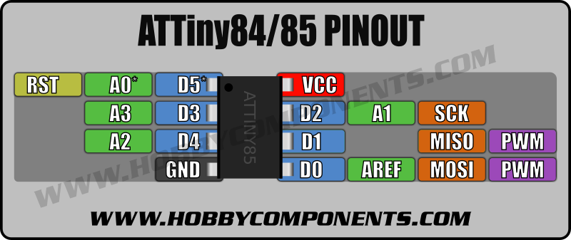
 The ATtiny84 and ATtiny85 microcontrollers are great little devices when you need the flexibility of a microcontoller in your project but don’t need all the bells and whistles of the more complex microcontrollers found in common Arduino boards, such as the Arduino Mega or Uno. That said, for such a small pin count they are not short on features. The ATtiny 84 and 85 have up to 6 digital pins, up to 4 analogue inputs, 2 PWM outputs (or analogue outputs as Arduino refers to them), and an SPI interface.
The only downside is that the Arduino development environment (IDE) doesn’t directly support these devices. Thankfully though, the latest version of the Arduino IDE now provides the ability to add third party support for no-official Arduino hardware. You will need the latest version (1.6.x at the time of writing this post) or later. To add support for the ATtiny84/85 just follow the steps below:
Adding support to your Arduino Development Environment
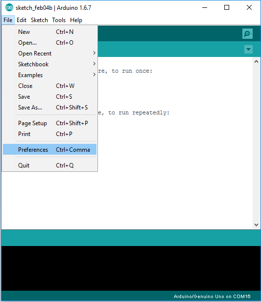
Step 1) First we must tell the IDE where to get the additional board support files from. In the Arduino IDE go to File → Preferences.
Step 2) In the window that opens up paste the following URL into the text box labelled ‘Additional Boards Manager URLs’:
There are several third party sources for the ATtiny84/85 but the above source is the one recommended by Arduino so this is the one we will be using in this guide.
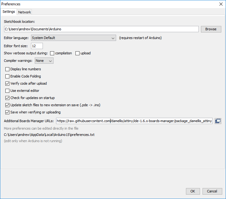
When you have pasted in the URL click the ‘OK’ button.
Step 3) Go to Tools → Board → Board Manager…

In the window that opens up scroll to the bottom and you should see an entry for the ATtiny titled ‘attiny by David A. Mellis’.
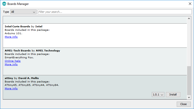
Click on this entry and you will see a drop down box to select a version. If there is more than one version then just select the latest. Then click on the install button. The install process should only take a few seconds and when it is completed you can then close the boards manager window by clicking the ‘Close’ button.
If all went well you should now see an option for ATtiny devices under Tools → Board.
Programming your ATtiny
The ATtiny devices do not have hardware USB or serial support so you can’t program them in the same way you would an ordinary Arduino device. Instead, you need an additional programmer that will interface to both your computer and the ATtiny. There are two options for doing this, the easiest way is using a dedicated ICSP programmer, or alternatively if you have an Arduino, you can use it as a programmer. We will demonstrate how to program your ATtiny with an Arduino sketch (the blink sketch) for both cases, but before we can do this we first need to set up the board type in the Arduino IDE for the ATtiny:
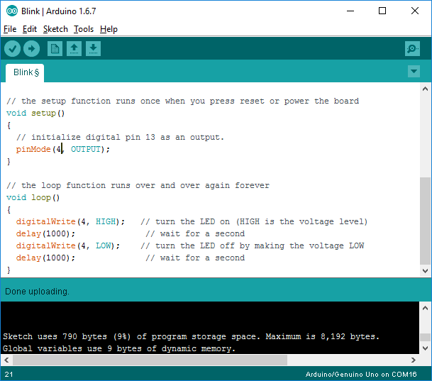
Step 1) In the Arduino IDE open up the example blink sketch by selecting File → Examples → 01 Basics → Blink
The Example blink sketch is written for an Arduino with a digital pin 13. As the ATtiny only has 5 digital pins you will need to change the 3 pin references within the sketch (one in the pinMode line, and one in each of the two digitalWrite lines) to one of the digital pins that exists on the ATtiny. In our example we have changed it to digital pin 4:
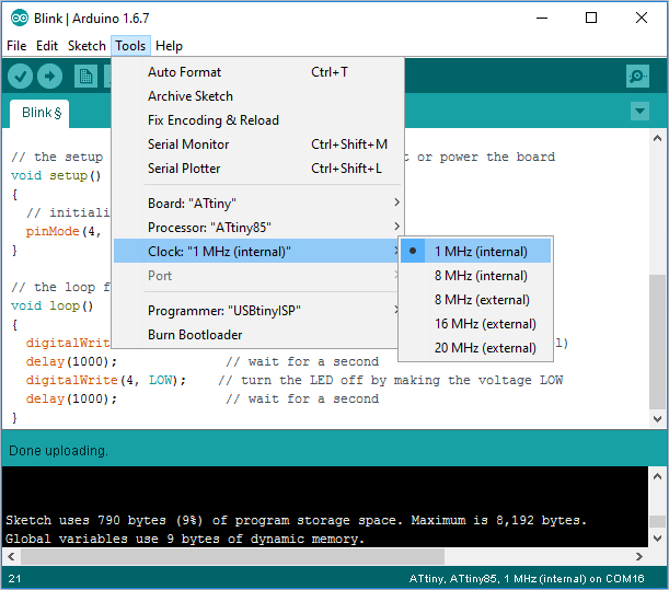
Step 2) In the Arduino IDE Select the ATtiny as the board type by selecting Tools → Board → ATtiny:

Two additional options will now appear under the Tools menu called ‘Processor’ and ‘Clock’. Make sure processor is set to either ‘ATtiny84’ or ‘Attiny85’ (depending on the version of chip that you have) and that the clock is set to ‘1 MHz (internal)’ as shown:
Now that you have set up the IDE we can move on to programming your ATtiny using one of the two previously discussed methods:
Using an ICSP programmer (the easy way):
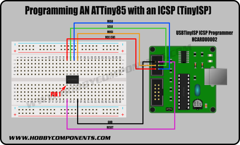
The easiest way to program your ATtiny is to use a dedicated programmer. For this example we will use a USBTinyISP programmer, which is directly supported by the Arduino IDE. See the bottom of this guide for a link to purchase one via our website.
Step 1) Connect the programmer to the ATtiny’s SPI pins as shown:
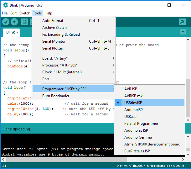
Step 2) In the Arduino IDE Select the USBtinyISP as the programmer type by selecting Tools → Programmer → ‘USBTinyISP’.
Step 3) You are now ready to program your ATtiny. You can do this by clicking on the upload button (right pointing arrow button on the top left of the window) in the usual way, but do this whilst holding down the shift key. When hovering the mouse pointer over the upload button with the shift key held down you will notice that is says ‘Upload using programmer’ instead of just the usual ‘Upload’.
If you have connected your ATtiny to the programmer correctly the blink sketch should be uploaded to your ATtiny without any errors. If so you can then jump to the ‘Connecting an LED’ section at the bottom of this tutorial.
Using an Arduino as a programmer:
If you have an Arduino board laying around you can temporarily turn it into an in-circuit programmer which you can then use to program your ATtiny in the same way as using the USBtinyISP programmer described in the previous section. There are however, three main differences:
First of all you will need to upload a special sketch to your Arduino board to turn it into an in-circuit programmer. The sketch comes with the Arduino IDE and can be found under Files → Examples → ArduinoISP → ArduinoISP. Just upload it to your Arduino board as you would any other sketch.
Next, for the programmer type under Tools → Programmer select ‘Arduino as ISP’:
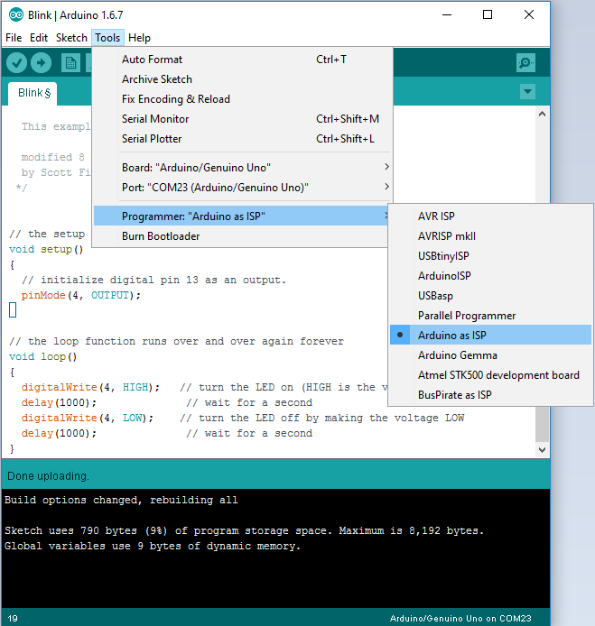
Remember also to set the COM port for your Arduino under Tools → Port.
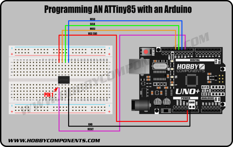
Finally, connect the ATtiny to your Arduino’s SPI pins and the ATtiny’s reset pin to the Arduino’s digital pin 10. For an Uno this would be as shown:
You can then program your ATtiny with the example blink sketch in the same way as you would if you where using a dedicated ICSP programmer. Just remember to hold the shift key whilst clicking the upload button!
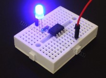
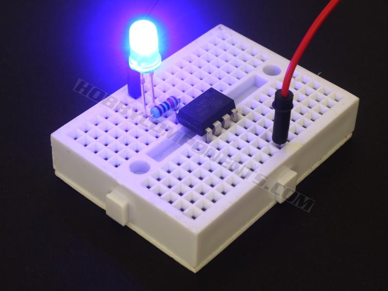
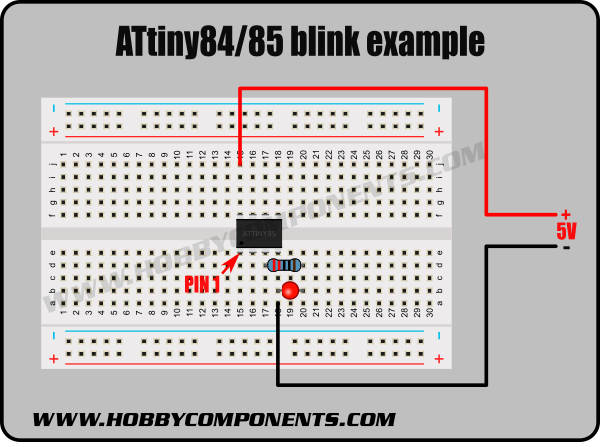
Connecting an LED:
Now that you have your ATtiny programmed you can check that it is running the blink sketch correctly by adding an LED. Assuming you configured the blink sketch to use digital pin 4 you can follow the example in the diagram below. Remember to include a current limiting resistor (ideally 220 Ohm) otherwise you will draw too much current from the ATtiny’s digital pin and damage it.
You can leave the programmer connected but if you connect the LED to any of the pins used by the programmer you will need to remove the LED when programming another sketch as it will interfere with the programming signals.
Supercharging your ATtiny:
By default the ATtiny is configured to operate with an internal 1MHz clock. This is fine for simple sketches, but some sketches and libraries may need it to run them faster. The SoftwareSerial library is one example of this. To do this you can reconfigure the ATtiny to run with an internal 8MHz clock. Just follow these steps:
Step 1) Connect your programmer to the ATtiny as described in earlier sections of this guide.
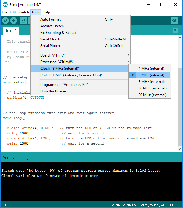
Step 2) In the Arduino IDE select Tools → Clock → 8 MHz (internal):
Step 3) In the Arduino IDE select Tools → Burn Bootloader.
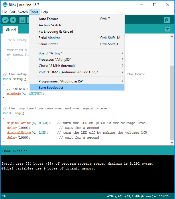
This won’t actually burn a bootloader to your ATtiny but will configure the fuse bits inside the ATtiny so that it always uses an internal 8MHz clock. You will only need to complete this process once, unless you wish to change the clock speed again.
Step 4) You can now program your sketch as before, but remember to keep ‘8MHz (internal)’ selected for the clock speed otherwise any timings in your sketch will be wrong.
Where to buy the items mentioned in this post:
ATtiny85 8 pin DIP IC:Â here
USBTinyISP in-circuit programmer can be purchased here.Â
400 point breadboard can be purchased here.
Jumper Wires can be purchased here.
5mm LEDs in packs of 10 can be purchased here.
5mm 5V LEDs (no need for current limiting resistor) can be purchased here.
All content within this post, including images, are copyright Hobby Components Ltd and may not be reproduced without permission.


Thank you for all these informations. I want to test this programming process with my arduino Uno.
Thanks, glad to hear the guide helped you.
Worked first time. I’m a bit puzzled though. I was redirected to this site from two videos that listed the site as further reading. However, both these videos used a 10 microfarad capacitor across the Arduino’s Reset and the Gnd pin. Unfortunately, I was unable to get it to work.
Do you have any idea why or where the capacitor addition came from ?
I’m not sure what videos you are referring to but the capacitor on the reset pin could be there for a number of reasons:
Firstly it would keep the reset pin low for a short amount of time when power is first applied. This would help to keep the device in reset whilst the power supply stabilised itself.
Secondly, if a reset switch was connected to this pin the capacitor would help to debounce the switch and maybe help hold the pin low for a sufficient amount of time to correctly reset the device.
As for the reason why it didn’t work for you again, there could be a number of reasons. Did you include the pull-up resistor? Also if your using a 10uF capacitor it’s likely that its polarsised. Have you connected it the correct way around?