


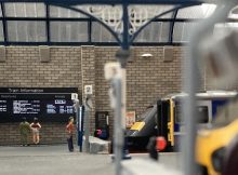
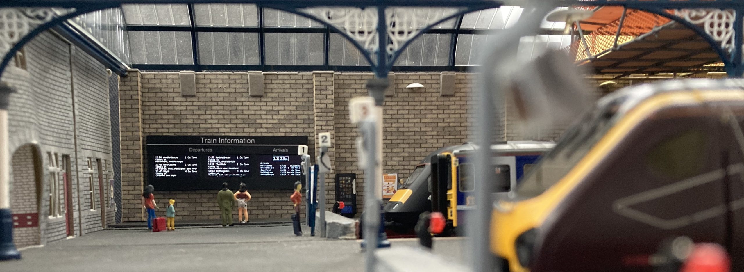
This is the first post in a series looking at how to use a SSD1306 128×64 Pixel OLED Display Module as a passenger information display on a model railway. The screens on these modules are 22mm by 11mm. This makes them a scale size of 1.6m wide by 0.8m high at OO scale. So they are a suitable size.
We will begin by looking at the code required to make a static departures screen. Other articles in the series will cover displaying a clock, dynamic departures and arrivals and using multiple screens to create the kind of information display you see on a mid-sized station concourse.
Whatever the style of display, there are two things that the sketch has to do; it needs to hold the data about the trains, and display that data on the screen. You could merge this together, but that would make changing or updating the display very difficult. We will keep these separate to give us flexibility.
The Information
We will start with the data. We are going to display train departure information, including destination, departure time and platform number. If we only ever want to display information for one train we use a variable of suitable type for each piece of data. But our aim is to be able to display several different trains on our screen. We can make things easier by structuring our data, grouping together the information about each train in one place. To do this we will use a struct data type.
struct TrainDeparture
{

};
Within this struct we will place the variables required to hold the information about each train.
struct TrainDeparture
{
byte hours;
byte minutes;
byte platform;
char *destination;
};
Think of this as a blueprint. We will use this to create all our departures, each with their own specific information.
TrainDeparture departure1;This creates our first departure. This is referred to as an object. We can now fill that object with our data.
departure1.hours = 11;
departure1.minutes = 10;
departure1.platform = 1;
departure1.destination = “Sheffield”;
Similarly we can add the data for a second train.
departure2.hours = 11;
departure2.minutes = 16;
departure2.platform = 3;
departure2.destination = “Nottingham”;
And so on.
To make this more manageable, and easier to add more trains, we are switching to using an array to hold all our departures in one place.
const byte NUMBER_OF_DEPARTURES = 6;
TrainDeparture departures[NUMBER_OF_DEPARTURES];
We could then enter our data as shown
departure[1].hours = 11;
departure[1].minutes = 15;
departure[1].platform = 1;
However, this would require a lot of typing. There is a shorthand way of entering the data as follows.
TrainDeparture departures[NUMBER_OF_DEPARTURES] = {
  {11, 11, 1, "Sheffield"},
  {11, 14, 3, "Nottingham"},
  {11, 28, 1, "Amblethorpe"},
  {11, 40, 2, "Newcastle"},
  {11, 49, 4, "Blyth"},
  {11, 58, 1, "Amblethorpe"}
};
This coma separated list places the data into the variables in the order we specified them in the TrainDeparture struct. The information to be displayed on our screen is in the sketch. We will now work through getting that information on the screen.
The Display
Working out which of our screen’s 8,192 individual pixels need to be switched on and off is rather complex, as is communicating that information to the display module. However, we can ignore all that complexity by using the Hobby Components Library, which will deal with all the complex stuff for us. This needs to be installed in the Arduino IDE and can be download from the support page on the forum here.
This library, along with SPI (which enables the development board to communicate with the screen) needs to be included in our sketch.
#include "HCuOLED.h"
#include "SPI.h"
Three pins also need to be defined. These connect to the RST (reset), DC (data/command) and CS (chip select) pins on the display.
#define CS_DI 10
#define DC_DI 9
#define RST_DI 8
Between the display module and the development board there also needs to be a GND to GND wire, VCC to 5V (or 3.3V) D0 to pin 13 and D1 to pin 11. Pins 11 and 13 are mandatory for the SPI connection. This also ties up pin 12, so do not try and use 12 for another purpose (I learnt this the hard way when a thing that “should” have worked didn’t).
We need to create an instance of the display:
HCuOLED HCuOLED(SH1106, CS_DI, DC_DI, RST_DI);The library is designed to work with several Hobby Components display modules. This specifies which module we are using and the pins it is connected to.
To get our train information on to the display we need to follow a process. To print text on the screen we first need to specify which of the available fonts to use. Because we are working at a scale of 1/76th and we have lots of information to cram on the screen we need a tiny font. For this project I created two fonts, the first 6 pixels high and the second a mere 5 pixels high. They are included in the library with 3 other larger fonts. To set the font we use the following line:
HCuOLED.SetFont(sharpsharp_6pt);Once set, we can continue to use this font until we specify a different one.
Next we need to specify where we want our text to appear on the display. Our display is 64 pixels high and 128 pixels wide. Starting at (0, 0) and finishing at (63, 127) we use the Cursor() function to set where we want the top left corner of the text to appear. We’ll start with it at the very top left of the screen.
HCuOLED.Cursor(0,0);We can then place the text we want on the screen using the Print command.
HCuOLED.Print(departures[0].hours);This will place hours value of departure[0] on the display.
We can then continue to specify the location and the information we want on the screen. First a colon to separate the Hours and Minutes, and then the minutes.
HCuOLED.Cursor(10, 0);
HCuOLED.Print(":");

HCuOLED.Cursor(12,0);
HCuOLED.Print(departures[0].minutes);
Notice that the first value of the cursor is increasing. This is moving the cursor across the screen so the text is “printed” to the right of, rather than on top of, the previous text. We will now add the Destination and Platform Number.
HCuOLED.Cursor(25,0);
HCuOLED.Print(departures[0].destination);
HCuOLED.Cursor(91,0);
HCuOLED.Print(departures[0].platform);
To complete the line we will add in one more piece of information for our passengers.
HCuOLED.Cursor(100,0);
HCuOLED.Print("On Time");
Our trains are never late!! So we don’t need to use a variable for this text!
We need to do this for all of our departures, displaying them below, row by row. So we will place this code in a function to allow us to use it repeatedly. The zeros for our departures and our row position are replaced with variables “train” and “row” so they can be incremented for each departure.
void displayDeparture(byte row)
{
  const byte ROWHEIGHT = 8;
  byte train = row;
  row = row * ROW_HEIGHT;

  HCuOLED.SetFont(sharpsharp_6pt);

  HCuOLED.Cursor(0, row);
  HCuOLED.Print(departures[train].hours);

  HCuOLED.Cursor(10, row);
  HCuOLED.Print(":");

  HCuOLED.Cursor(12, row);
  HCuOLED.Print(departures[train].minutes);

  HCuOLED.Cursor(25, row);
  HCuOLED.Print(departures[train].destination);

  HCuOLED.Cursor(91, row);
  HCuOLED.Print(departures[train].platform);

  HCuOLED.Cursor(100, row);
  HCuOLED.Print("On Time");
}
This can then be called from the loop() by displayDeparture() but we will get back to that. We have to consider setup first.
If the display has already been used there will be information held in its display buffer. When we power it up we want to clear that information from the screen. To do this we issue a reset in setup.
void setup()
{
  /* Reset the display */
  HCuOLED.Reset();
}
With the display reset we are ready to head into the loop and build up all the rows on our screen. We need to use a for loop to call the displayDeparture() function for each of the trains. This builds up all of our text in a screen buffer. This is one of the complex bits that the Hobby Components library does for us so we don’t have to worry about it. Once the screen buffer is completed we can send it to the display using the Refresh function.
void loop()
{
  for (int i = 0; i < NUMBER_OF_DEPARTURES; i++)
  {
    displayDeparture(i);
  }
  HCuOLED.Refresh();
}
We now have all the code required to create a model railway departure board. Our sketch can be uploaded to a deelopment board. If you haven’t followed along writing the code, you can download the sketch from Github here.
https://github.com/SharpSharp/ModelRailwayPID/blob/main/HCuOLED_Model_Railway_Departures_Display.ino

This is a static display. Later in the series we are going to use our Nano to turn this into a dynamic display. To achieve that, the nano must keep to time.
Part 2 in this series will go through how to make a clock display.
Files relevant to this series
1 https://github.com/SharpSharp/ModelRailwayPID/blob/main/HCuOLED_Model_Railway_Departures_Display.ino
2 https://github.com/SharpSharp/ModelRailwayPID/blob/main/HCuOLED_Model_Railway_Clock_Display.ino
4 https://github.com/SharpSharp/ModelRailwayPID/blob/main/HCuOLED_Model_Railway_Arrivals_Display.ino
Library:
https://github.com/HobbyComponents/HCuOLEDhttp://forum.hobbycomponents.com/viewto … =58&t=1817
OR
https://forum.hobbycomponents.com/viewtopic.php?f=58&t=1817
A Note on Electronics
Development of the code for this project was completed using a Nano.
However, the final installation was completed using a Pro Mini.
The Uno would also be suitable, but obviously has a bigger footprint so use of this will be determined by your chosen installation area.
The OLED used was a white backlit module, however, Hobby Components also sell a blue backlit OLED which would also work well.


A brilliant project. I might even consider building a modern image exhibition layout layout just to put some of these displays on it!
Fantastic, great job