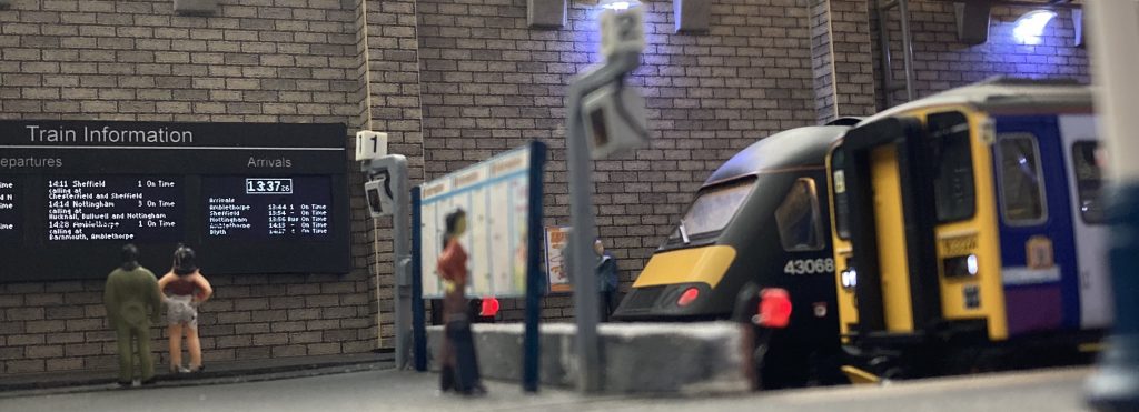
This series looks at how to use a SSD1306 128×64 pixel OLED display module as a passenger information display on a model railway. The first post in the series created a train departures display. We now move on to creating and displaying a clock.
It is possible to fit a real time clock module to our nano, but we are going to create a simple clock in the code. We need to include the libraries that will do the complex stuff for us and define the pins that we will use to connect the module to the nano. These are the same as in the departures example.
#include "HCuOLED.h"
#include "SPI.h"

 // These connect to the CS, DC, and RST pins on the display.

#define CS_DI 10
#define DC_DI 9
#define RST_DI 8

/* Create an instance of the library for the display */
HCuOLED HCuOLED(SSD1307, CS_DI, DC_DI, RST_DI);
The Information
As with our previous example we need to deal with two things; the information and the display. Once again we are going to keep these two separate in our code.
We need to declare some global variables to allow us to keep track of hours, minutes and seconds.
/* clock stuff */
byte h=10;
byte m=23;
byte s=45;
These variables enable us to count through time, incrementing seconds, minutes and hours. We will put this code into our loop().
void loop()
{
  s=s+1;
  if(s==60)
  {
    s=0;
    m=m+1;
  }
  if(m==60)
  {
    m=0;
    h=h+1;
  }
  if(h==24) h=0;

 delay(1000);
}
The delay at the end causes the nano to pause for 1000 milliseconds (1 second) each time it goes round the loop, and the s value increases by one each loop so it is the basis of our clock.
That is all the information we need. It’s time to look at how we display it.
The Display
When we created the departure board we placed the time of our trains on the screen, so we are familiar with the process. But it is more complicated if we want to display a value less that 10, something we were careful to avoid on the departures screen. We want our display to read 09:08:07, but our code will not display the leading zero, leaving us with 9 :8 :7 . We will need some if statements to check for small values and to add in some “0” characters where required.
The process is now familiar. In our displayClock() function we set the font, then set the cursor position followed by the text we want to print to the screen and this builds up the clock in the buffer, which we then upload to the screen with a Refresh command.
void displayClock()
{
  byte col = 42;
  byte row = 2;
  HCuOLED.SetFont(MedProp_11pt);

  /* display hours   */
  HCuOLED.Cursor(col, row);
  if (h>9)
  {
    HCuOLED.Print(h);
  } else if (h==0)
  {
    HCuOLED.Print("00");
  } else {
    HCuOLED.Print("0");
    HCuOLED.Cursor(col+7, row);
    HCuOLED.Print(h);
  }
  HCuOLED.Cursor(col+16, row);
  HCuOLED.Print(":");

  /* display minutes */
  HCuOLED.Cursor(col+20, row);
  if (m>9)
  {
    HCuOLED.Print(m);
  } else if (m==0)
  {
    HCuOLED.Print("00");
  } else {
    HCuOLED.Print("0");
    HCuOLED.Cursor(col+27, row);
    HCuOLED.Print(m);
  }

  /* display seconds */
  HCuOLED.SetFont(sharpsharp_6pt);
  HCuOLED.Cursor(col+37, row+6);
  if (s>9)
  {
    HCuOLED.Print(s);
  } else if (s==0)
  {
    HCuOLED.Print("00");
  } else {
    HCuOLED.Print("0");
    HCuOLED.Cursor(col+41, row+6);
    HCuOLED.Print(s);
  }
  HCuOLED.Refresh();
}
We are using variables col and row to set the coordinates for the top left corner of the clock. The positions of the numbers are then set from those coordinates. This allows us to move the position of the whole clock on the screen by simply changing the values of col and row.
We can then add a call to this function in the loop.
void loop()
{
  displayClock();

  s=s+1;
  if(s==60)
  {
    s=0;
    m=m+1;
  }
  if(m==60)
  {
    m=0;
    h=h+1;
  }
  if(h==24) h=0;

 delay(1000);
}
The loop delay(1000) means that our displayClock() function will be called once every second and the current time will be displayed on the screen.
But we have an issue with the display. Each time we generate a HCuOLED.Print() command a new bit of information is added to the screen. As we repetitively call displayClock() all we are doing is adding text to the screen, we aren’t removing the old text. In time the clock will become unreadable as all the numbers are written on top of each other. Each time we start to build up the clock information in our buffer, we need to clear away the information that is already in the display buffer. We will do this by adding a line of code to the loop immediately before we call displayClock():
HCuOLED.ClearBuffer();We now have a working clock. To make it stand out we will give it a border. To draw a rectangle we use the Rect function with the borders four co-ordinates and specify an OUTLINE.
HCuOLED.Rect(col-2, row-2, col+47, row+14, OUTLINE);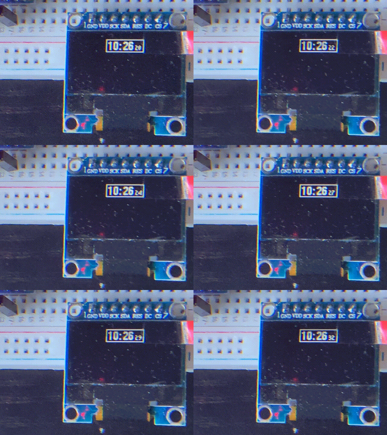
This can be added anywhere in the displayClock() function. We will place it at the start. This completes our clock code. The sketch can now be uploaded to our nano. If you haven’t followed along and written your own sketch you can download a copy from Github here.
https://github.com/SharpSharp/ModelRailwayPID/blob/main/HCuOLED_Model_Railway_Clock_Display.ino
A clock provides time. The next article in this series will return to our departures board and use the time to control which of our departures are added and removed from the screen.
Files relevant to this series
1 https://github.com/SharpSharp/ModelRailwayPID/blob/main/HCuOLED_Model_Railway_Departures_Display.ino
2 https://github.com/SharpSharp/ModelRailwayPID/blob/main/HCuOLED_Model_Railway_Clock_Display.ino
4 https://github.com/SharpSharp/ModelRailwayPID/blob/main/HCuOLED_Model_Railway_Arrivals_Display.ino
Library:
https://github.com/HobbyComponents/HCuOLEDhttp://forum.hobbycomponents.com/viewto … =58&t=1817
OR
https://forum.hobbycomponents.com/viewtopic.php?f=58&t=1817
A Note on Electronics
Development of the code for this project was completed using a Nano.
However, the final installation was completed using a Pro Mini.
The Uno would also be suitable, but obviously has a bigger footprint so use of this will be determined by your chosen installation area.
The OLED used was a white backlit module, however, Hobby Components also sell a blue backlit OLED which would also work well.

![Simon Says… Wanna Play a [Arduino] Game!](https://blog.hobbycomponents.com/wp-content/uploads/2024/03/BLOG-IMAGE-Simon-Says-150x150.png)

