


 One of the questions we commonly get asked is how to go about using an Arduino to control a motor from a potentiometer. Lots of people out there would like to do this but just don’t quite have enough programming knowledge to get an Arduino to do this. So to compliment the release of our new Arduino motor controller library (HCMotor) we’ve put together this quick tutorial to show you how to take advantage of this library to do just that.
The tutorial is in three parts, the first is for driving a DC motor, the second for driving a DC motor but in both forward and reverse directions, and finally the third part shows how to control a standard stepper motor. You can just go straight to the section you are interested in but don’t forget to go to the bottom of the page to get the download link for the library. Also, the tutorial only demonstrates driving one motor but it is possible to drive multiple motors independently using this library.
Before we start it should be noted that the HCMotor library currently only supports ATMega328 based Arduinos which includes the Uno, Nano, and Pro Mini. However, for this tutorial we will be using a standard Uno. The tutorial also assumes that you already have the Arduino IDE installed and are familiar with uploading a sketch to an Arduino board (if not check out our guide here http://blog.hobbycomponents.com/?p=45) and that you know how to add a library to it (there is a guide on the Arduino website here https://www.arduino.cc/en/guide/libraries).
Controlling a DC motor (one direction)
What you will need:
An Arduino compatible development boardÂ
To interface to the motor either a transistor/FET such as this or as in the case of this example our IFT520 module
A potentiometer such as this or this
Some wire to connect it all up, such as this.
The HCMotor library (see the very bottom of this post for a link).
Connecting everything together

Step 1) First of all you will need to connect the potentiometer to one of the Arduino’s analogue pins (A0) so that it can measure the position of the pot. Connect power across the pot by connecting the GND and 5V pins on the Arduino to the outer two pins of the pot (it doesn’t matter which way around they go so long as they are connected to the out pins). The middle pin is the pot’s wiper. This will give a value between 0 and 5V depending on the position of the pot. Connect this to the analogue input pin A0 on the Arduino.
Step 2) Connect the driver board. You should never connect a motor directly to an Arduino’s digital pins as it is very likely that doing so will damage your Arduino. Therefore we are using an interface board, which is essentially just a FET brought out to a convenient set of terminals. Connect the signal pin from the module to digital pin 7 on the Arduino. Don’t forget to hook up a ground (GND) connection from your Arduino to the driver board.
Step 3) Connect the DC motor to the driver board. In this case to the V+ and V- terminals of the drive board. It doesn’t matter which way around the motor is connected.
Step 4) Connect some external power. Don’t be tempted to power your motor from the Arduino’s power supply. Even with small motors they can draw enough current to overload it. Use an external power supply or a battery. In the above example we are using a standard 130 motor which can be powered from four AA batteries. Connect this external power to the driver boards Vin (positive) and GND (0V) terminals.
Step 5) Cut and paste the example sketch below into the Arduino IDE and upload it to your board.
[cpp]
/* Include the library */
#include "HCMotor.h"</code>
/* Set the pin that will control the motor. Note that it doesn’t have to be a PWM pin –
any digital pin will do! */
#define MOTOR_PIN 7
/* Set the analogue pin the potentiometer will be connected to. */
#define POT_PIN A0
/* Create an instance of the library */
HCMotor HCMotor;
void setup()
{
/* Initialise the library */
HCMotor.Init();
/* Attach motor 0 to digital pin 7. The first parameter specifies the
motor number, the second is the motor type, and the third is the
digital pin that will control the motor */
HCMotor.attach(0, DCMOTOR, MOTOR_PIN);
/* Set the duty cycle of the PWM signal in 100uS increments.
Here 100 x 100uS = 1mS duty cycle. */
HCMotor.DutyCycle(0, 100);
}
void loop()
{
int Speed;
/* Read the analogue pin to determine the position of the pot. The map
function takes this value which could be anywhere between 0 – 1024
and reduces it down to match the duty cycle range of 0 – 100 */
Speed = map(analogRead(POT_PIN), 0, 1024, 0, 100);
/* Set the on time of the duty cycle to match the position of the pot. */
HCMotor.OnTime(0, Speed);
}
[/cpp]
If everything is connected correctly you should have complete control of your DC motors speed by turning the pot. In its minimal position the motor should come to a complete stop, and in the maximum position should be at full speed.
Controlling a DC motor (forward and reverse)
What you will need:
An Arduino compatible development board
To interface to the motor a H-Bridge driver board such as the L298N or in the case of this example the L9110S. You should choose a board that is capable of meeting the power requirements of your motor.
A potentiometer such as this or this
Some wire to connect it all up, such as this.
The HCMotor library (see the very bottom of this post for a link).
Connecting everything together
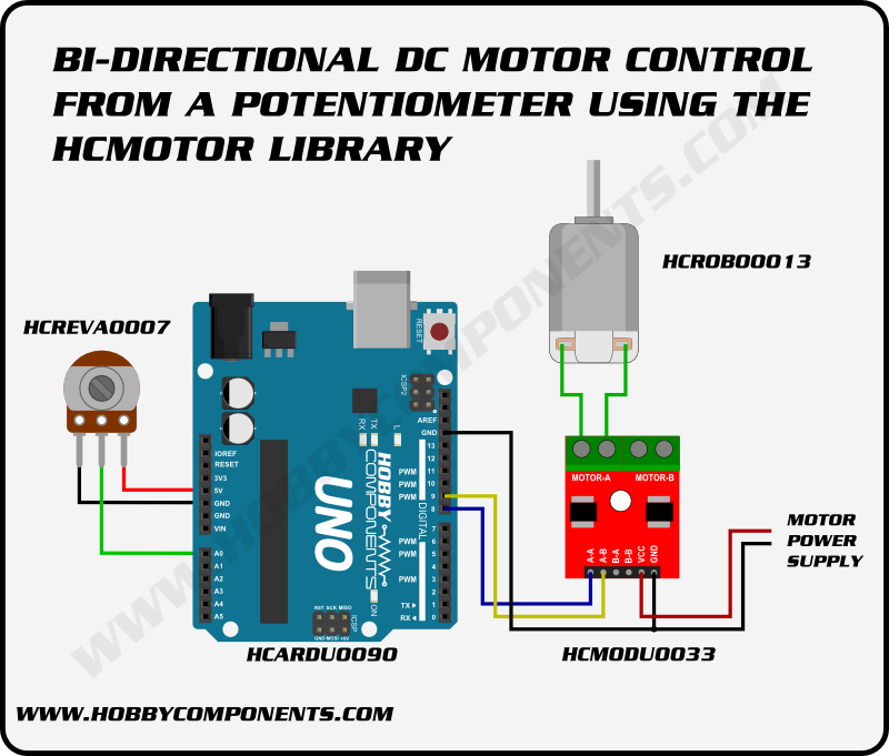
Step 1) First of all you will need to connect the potentiometer to one of the analogue pins (A0) of the Arduino so that it can measure the position of the pot. Connect power across the pot by connecting the GND and 5V pins of the Arduino to the outer two pins of the pot (it doesn’t matter which was around they go so long as they are connected to the out pins). The middle pin is the pot’s wiper. This will give a value between 0 and 5V depending on the position of the pot. Connect this to the analogue input pin A0 of the Arduino.
Step 2) Connect the driver board. You should never connect a motor directly to an Arduino’s digital pins as it is very likely that this will damage your Arduino. To be able to drive the motor in both forward and reverse directions we need to be able to switch the polarity of the voltage to the motor. We could do this by physically swapping the wires to the motor terminals but a H-Bridge driver module allows us to do this automatically. Like the one in the example, most H-Bridge drivers require two control inputs. Pulling the first input high and the second low will turn the motor in one direction, and pulling the first input low and the second high will turn the motor in the opposite direction. The HCMotor library will take care of all this so you just need to connect it to the appropriate digital pins. In the above example connect input A-A to digital pin 8 and pin A-B to digital pin 9. The driver board can drive two individual motors but as in this tutorial we are only driving one motor you can ignore the other two inputs. Don’t forget to hook up a ground (GND) connection from your Arduino to the driver board.
Step 3) Connect the DC motor to the driver board. In this case to the two screw terminals marked Motor A. It doesn’t matter which way around the motor is connected.
Step 4) Connect some external power. Don’t be tempted to power your motor from the Arduino’s power supply. Even with small motors they can draw enough current to overload it. Use an external power supply or a battery. In the above example we are using a standard 130 motor which can be powered from four AA batteries. Connect this external power to the driver boards VCC (positive) and GND (0V) terminals.
Step 5) Cut and paste the example sketch below below into the Arduino IDE and upload it to your board.
[cpp]
/* Include the library */
#include "HCMotor.h"
/* Pins used to drive the motors */
#define MOTOR_PINA 8 //For HCMODU0033 connect to A-IA, for HCARDU0013 connect to IN1
#define MOTOR_PINB 9 //For HCMODU0033 connect to A-IB, for HCARDU0013 connect to IN2
/* Set the analogue pin the potentiometer will be connected to. */
#define POT_PIN A0
/* Set a dead area at the centre of the pot where it crosses from forward to reverse */
#define DEADZONE 20
/* The analogue pin will return values between 0 and 1024 so divide this up between
  forward and reverse */
#define POT_REV_MIN 0
#define POT_REV_MAX (512 – DEADZONE)
#define POT_FWD_MIN (512 + DEADZONE)
#define POT_FWD_MAX 1204
/* Create an instance of the library */
HCMotor HCMotor;
void setup()
{
 /* Initialise the library */
 HCMotor.Init();
 /* Attach motor 0 to digital pins 8 & 9. The first parameter specifies the
   motor number, the second is the motor type, and the third and forth are the
   digital pins that will control the motor */
 HCMotor.attach(0, DCMOTOR_H_BRIDGE, MOTOR_PINA, MOTOR_PINB);
 /* Set the duty cycle of the PWM signal in 100uS increments.
   Here 100 x 100uS = 1mS duty cycle. */
 HCMotor.DutyCycle(0, 100);
}
void loop()
{
 int Speed, Pot;
 /* Read the analogue pin to determine the position of the pot. */
 Pot = analogRead(POT_PIN);
 /* Is the pot in the reverse position ? */
 if (Pot >= POT_REV_MIN && Pot <= POT_REV_MAX)
 {
  HCMotor.Direction(0, REVERSE);
  Speed = map(Pot, POT_REV_MIN, POT_REV_MAX, 100, 0);
 /* Is the pot in the forward position ? */
 }else if (Pot >= POT_FWD_MIN && Pot <= POT_FWD_MAX)
 {
  HCMotor.Direction(0, FORWARD);
  Speed = map(Pot, POT_FWD_MIN, POT_FWD_MAX, 0, 100);
 /* Is the pot in the dead zone ? */
 }else
 {
  Speed = 0;
 }
 /* Set the on time of the duty cycle to match the position of the pot. */
 HCMotor.OnTime(0, Speed);
}
[/cpp]
If everything is connected correctly you should have complete control of your DC motors speed in both directions simply by turning the pot. In the pot’s minimum position the motor should be in full reverse direction. Turning the pot towards its middle position should cause the motor to slow down until comes to a complete stop as the pot reaches the middle. Continuing to turn the pot in the same direction will cause the motor to start turning in the forward direction and will increase in speed as the pot reaches the opposite end of its range.
Controlling a Stepper motor (forward and reverse)
What you will need:
An Arduino compatible development board
To interface to the motor a stepper motor driver board such as the A4988 or in the case of this example the TB6560. You should choose a board that is capable of meeting the power requirements of your motor.
A potentiometer such as this or this
Some wire to connect it all up, such as this.
The HCMotor library (see the very bottom of this post for a link).
Connecting everything together.
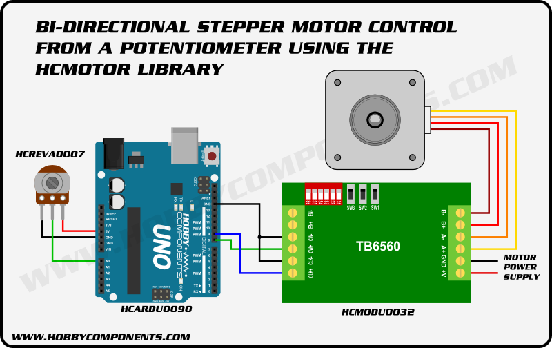
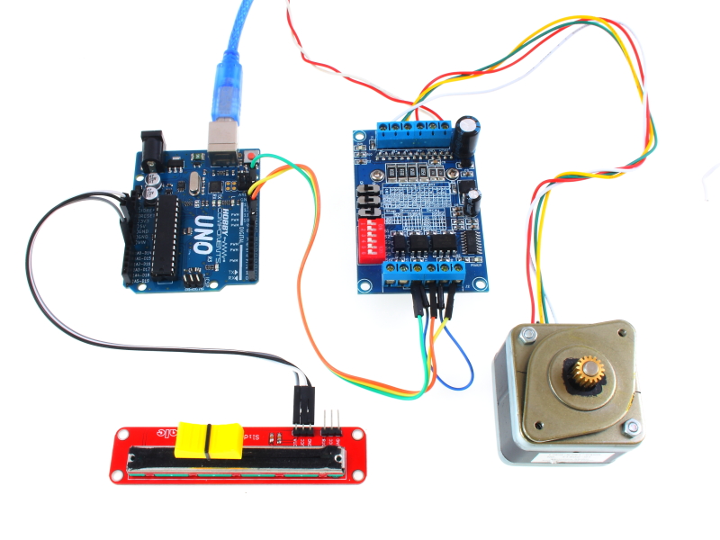
Step 1) First of all you will need to connect the potentiometer to one of the analogue pins (A0) of the Arduino so that it can measure the position of the pot. Connect power across the pot by connecting the GND and 5V pins of the Arduino to the outer two pins of the pot (it doesn’t matter which way around they go so long as they are connected to the out pins). The middle pin is the pot’s wiper. This will give a value between 0 and 5V depending on the position of the pot. Connect this to the analogue input pin A0 of the Arduino.
Step 2) Connect the driver board. You should never connect a motor directly to an Arduino’s digital pins as it is very likely that this will damage your Arduino. Stepper motors work in a different way to normal DC motors in that they have several coils as opposed to just the one of a DC motor. Energising each coil in turn makes the motor move in one tiny increment (the step angle). Energising the next coil in the sequence makes the motor turn by another small increment. Stepper driver boards take care of this process for you. Most of them, as with the one in this example, require two control signals, a step and a direction. Pulsing the step input makes the motor turn by one increment. The direction input, as the name suggests, determines in which direction the motor will step. The HCMotor library will automatically generate these signals so you just need to connect the module to the appropriate digital pins. In the above example we connect input CW+ (clockwise direction) to digital pin 8 and pin CLK+ (clock) to digital pin 9. Don’t forget to hook up a ground (GND) connections from your Arduino to the driver board.
Step 3) Connect the stepper motor to the driver board. In this case to the four screw terminals marked A+, A-, B+ & B-. You will need to consult the documentation for your stepper motor for the correct order of the wires as the colour coding of wires is different for different types of stepper motor. Also, consult the documentation for your driver board for additional settings for your motor, such as running current.
Step 4) Connect some external power. Don’t be tempted to power your motor from the Arduino’s power supply. Even with small motors they can draw enough current to overload it. Use an external power supply or a battery. Connect this external power to the driver boards V+ (positive) and GND (0V) terminals.
Step 5) Cut and paste the example sketch below below into the Arduino IDE and upload it to your board.
[cpp]
/* Include the library */
#include "HCMotor.h"
/* Pins used to drive the motors */
#define DIR_PIN 8 //Connect to drive modules ‘direction’ input.
#define CLK_PIN 9 //Connect to drive modules ‘step’ or ‘CLK’ input.
/* Set the analogue pin the potentiometer will be connected to. */
#define POT_PIN A0
/* Set a dead area at the centre of the pot where it crosses from forward to reverse */
#define DEADZONE 20
/* The analogue pin will return values between 0 and 1024 so divide this up between
  forward and reverse */
#define POT_REV_MIN 0
#define POT_REV_MAX (512 – DEADZONE)
#define POT_FWD_MIN (512 + DEADZONE)
#define POT_FWD_MAX 1024
/* Create an instance of the library */
HCMotor HCMotor;
void setup()
{
 //Serial.begin(9600);
 /* Initialise the library */
 HCMotor.Init();
 /* Attach motor 0 to digital pins 8 & 9. The first parameter specifies the
   motor number, the second is the motor type, and the third and forth are the
   digital pins that will control the motor */
 HCMotor.attach(0, STEPPER, CLK_PIN, DIR_PIN);
 /* Set the number of steps to continuous so the the motor is always turning whilst
   not int he dead zone*/
 HCMotor.Steps(0,CONTINUOUS);
}
void loop()
{
 int Speed, Pot;
 /* Read the analogue pin to determine the position of the pot. */
 Pot = analogRead(POT_PIN);
 /* Is the pot in the reverse position ? */
 if (Pot >= POT_REV_MIN && Pot <= POT_REV_MAX)
 {
  HCMotor.Direction(0, REVERSE);
  Speed = map(Pot, POT_REV_MIN, POT_REV_MAX, 10, 1024);
 /* Is the pot in the forward position ? */
 }else if (Pot >= POT_FWD_MIN && Pot <= POT_FWD_MAX)
 {
  HCMotor.Direction(0, FORWARD);
  Speed = map(Pot, POT_FWD_MIN, POT_FWD_MAX, 1024, 10);
 /* Is the pot in the dead zone ? */
 }else
 {
  Speed = 0;
 }
 /* Set the duty cycle of the clock signal in 100uS increments */
 HCMotor.DutyCycle(0, Speed);
}
[/cpp]
If everything is connected correctly you should have complete control of your stepper motors speed in both directions simply by turning the pot. In the pot’s minimum position the motor should be in full reverse direction. Turning the pot towards its middle position should cause the motor to slow down until comes to a complete stop as the pot reaches the middle. Continuing to turn the pot in the same direction will cause the motor to start turning in the forward direction and will increase in speed as the pot reaches the opposite end of its range.
Library
The HCMotor library required for the above sketches can be downloaded from our support forum here:
http://forum.hobbycomponents.com/viewtopic.php?f=58&t=1870
The forum page also includes a more in-depth description of the functions available within the HCMotor library.


Hello, I downloaded to your library, and all the sample code always give error, any tips on how I can solve?
Could you cut and past the error you are seeing. Also can you tell me which version of the Arduino IDE you are using?
Hi, Matija, here from Slovenia. Link from Library doesn’t work. Is this stil actual?
I’ve checked the link and it seems to be working for me. I have just made it clickable though so could you try it again.
Did you succeed?
Did you changed the signs >,< and & to compile without errors?
Regards Matej
It looks like a bit of HTML formatting crept into the code. I’ve pasted the them in to the post again so hopefully this has fixed the problem.
Yeah!
With a littlebit of fantasy and web searchig (googling) it’s al “compilable” .
But now is copy , paste ready too, thanks to yout intervention.
Thanks!
Best regards Matej
Now working, thx.
Help needed
Can someone help please i am new to Arduino programing. I have a small window turbine with a wind direction potentiometer on it and a 24v geared dc motor that rotates the head of the turbine into the wind.I would like to make up a circuit that will turn the wind turbine to the same direction the the pot is pointing.
Hi There,
I too am having the same problem as the comment from Dan.
I downloaded the sketch for the stepper control and got an error. I’m using Arduino 1.6.8 on a win10 computer. The error is “exit status 1–error compiling for board Arduino/genuino Uno”
Hi Raul,
Is there any more information in the message area (where you copied you error message from)? You may have to scroll it up a bit.
Also can you give me the path to where you have placed the library files (HCMotor.cpp & HCMotor.h) ?
Thank you for the info. I’m new to Arduino and haven’t become familiar with the software. I did scroll up and told me that it could not find the “.h” file. I put every thing in the same directory and now it works.
Thank you, thank you, thank you
Your forum/website is chewing up your sketches and inserting undesired characters into the sketches. May I respectfully suggest you fix this on an otherwise brilliant page. Also maybe add the library link a little earlier for the DC section.
Thanks
>Also maybe add the library link a little earlier for the DC section
Thanks for the suggestion, I’ve added a note to the requirements list on each section.
>Your forum/website is chewing up your sketches and inserting undesired
>characters into the sketches.
A little while ago we did have a problem that caused some of the sketches to get corrupted with html data. We did work through the site to fix the problem but we could have missed something. However I’ve pasted the three sketches in this post into the Arduino IDE and they all seem to compile ok.
Is it in this post or somewhere else you’re seeing the issue?
Hi, my problem was solved with the project
Thank you
Glad we could be of help!
why error :\Kuliah\sketch_jan07b\sketch_jan07b.ino:2:21: fatal error: HCMotor.h: No such file or directory
#include “HCMotor.h”
^
compilation terminated.
exit status 1
Error compiling for board Arduino/Genuino Mega or Mega 2560.
Did you download and install the HCMotor library?
If not you can find the library and instructions on how to add it to the Arduino development environment in our support forum here:
http://forum.hobbycomponents.com/viewtopic.php?f=58&t=1870
please help me
i have a xy-1260 pwm controller that came with a potentiometer plugged in which also has a switch. Where do I wire the arduino outputs A-A A-B? not marked
Thank you, one of the few projects that worked on my first try