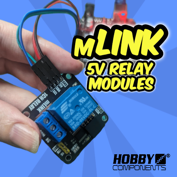
In this video I’m going to show you the mLink relay modules. These are a range of 5V relay modules that were designed to be controlled either manually or via a microcontroller. For manual control there’s a set of digital pin(s) that can be toggled to directly control the relay. For controlling via a microcontroller there is a serial I2C interface minimising the amount of pins required to control multiple relays or relay modules.
Users can download the library from various places as shown in the previous blog post here.
Connections diagram

Hobby Components Support Forum
mLink Range on Hobby Components
mLink 5V Relay Modules
Hobby Components Uno Plus Development Board
Dupont Cables
And here’s the Youtube Video
Arduino Sketch
/* FILE:    Blink_Relay_0.ino
   DATE:    04/10/21
   VERSION: 1.0
   AUTHOR:  Andrew Davies


This sketch uses the mLink library to control the state of relay 0 on one of the
mLink relay modules. This sketch can be used with one of the following modules:

mLink 1 Channel relay module (SKU: HCMODU0182)
mLink 2 Channel relay module (SKU: HCMODU0183)
mLink 4 Channel relay module (SKU: HCMODU0184)

Please see Licence.txt in the library folder for terms of use.
*/

#include "mLink.h"          // Include the library

mLink mLink;                // Create an instance of the library


#define I2C_ADD 0x52        // Default I2C address


void setup()
{
  mLink.init();             // Initialise the library
}


void loop()
{
  // Turn ON relay 0. Use SET_RLY1 for relay 1, SET_RLY2 for relay 2 etc
  mLink.SET_RLY0(I2C_ADD, HIGH);
  delay(10000);

  // Turn OFF relay 0
  mLink.SET_RLY0(I2C_ADD, LOW);
  delay(10000);
}

![Simon Says… Wanna Play a [Arduino] Game!](https://blog.hobbycomponents.com/wp-content/uploads/2024/03/BLOG-IMAGE-Simon-Says-150x150.png)


