


So you’ve taken the plunge…
You’ve decided to buy yourself an Arduino development board. You’ve figured out how to get the development environment installed and you’ve even managed to download the example blink sketch that most getting started tutorials will point you towards (http://blog.hobbycomponents.com/?p=51). This sketch is meant to be as simple a program as possible to demonstrate some of the basic components requited in writing an Arduno sketch. But if you have little or no programming skills,you may still be very confused as to what is going on with this sketch, because even though it is a relatively simple program, there is in actual fact a lot programming concepts within it.
In this guide we’ll pick apart each line of the blink sketch and explain what it is doing. This is by no means a definitive guide on how to write programs for your Arduino, but understanding what this simple sketch does may help to give you a better understanding of how to move forward with your own sketches.
First of all let’s take a look at what a program is…
Even as a complete novice there may be one or two concepts of programming that you may unwittingly already know. For instance, a program is a list of simple instructions that tell a computer what to do. The computer will work down this list from top to bottom ‘executing’ one instruction at a time. Bet you already knew that, right?
Your Arduino board is a computer, just like the desktop computer you may be using right now, but just in a more basic form. Like your desktop, when it is powered up it needs a program to follow to do something useful. There are many forms of programming languages out there but the one your Arduino environment uses is called ‘C++’. Believe it or not, although you may not currently understand this language, neither does your Arduino! At the very basic level just about all modern computers, including your Arduino, can only understand how to process numbers. Some numbers represent instructions such as add one number to another, some numbers represent data such as text or measurement data, and some numbers, when stored in special places, make things happen. Even the page you are reading right now will be broken down into numbers by your computer before it can process it.
But even as an expert programmer, a program that is just a long list of numbers is very difficult to understand and is not very practical for writing programs with. To resolve this we have high level languages such as C++. These are sort of a half way compromise between something that is easy to understand by a human but can also be easily converted or, ‘compiled’ into the lower level language that your Arduino can understand. If you’re very observant, when you downloaded the blink sketch to your Arduino you may have noticed that before it downloaded it, the Arduino software said something about ‘compiling sketch’. This is the Arduino environment first converting the high level C++ language into the language your Arduino can understand.
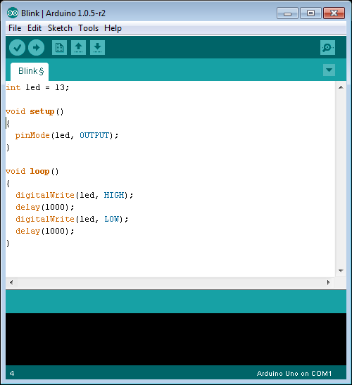
But enough about this low level stuff. One thing the Arduino environment tries to do is to remove the need to worry about what is going on at this low level and make it easier for a beginner to get into microcontrollers and programming them. So let’s take a look at the program, or as Arduino calls it, a ‘Sketch’, that most people who buy an Arduino will try out first…
Blink sketch:
In the above image we have removed the lines that are not part of the program.
As we’ve already mentioned, although this sketch is meant to be as simple as possible, there are quite a few things going on and we will need to break these up into sections to explain each part.
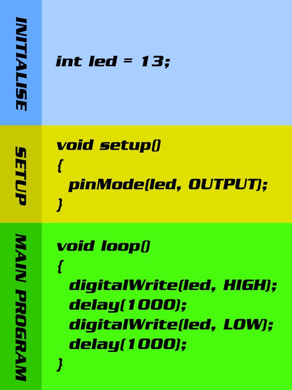
Initialisation
This is always at the top of the program, and being at the top, it gets run first. As such we tend to put things here that need to be pre-defined before we run our actual program. In our blink sketch we only have one line of code we need to worry about:

To explain what this line is actually doing we need to talk about one of the basic components of most programming languages: Variables. When you eventually start to write your own sketches you will find that quite often you’ll need to store a bit of information for use later in your program. Kind of like when going to the supermarket you might ‘store’ the list of items you need to purchase on a piece of paper to reference when you get to the supermarket. In C++, as with most programming languages, these are called variables. In each variable we create we can store a piece of information and then give it a meaningful name that can later be used to reference it. So long as we don’t fill up the Arduino’s memory we can create as many variables as we like and can give them a meaningful name. There are a few rules to naming variables, such as you can’t use spaces and a variable can’t start with a number, but generally you can call it whatever you like. For example, in the above line we have called the variable ‘led’, but we could have called it ‘ThePinThatTheLEDIsConnectedTo’, although that would be a little long winded!
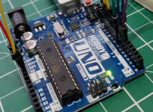
In our blink we use one of these variables to store the pin number of the LED we are going to control. On a lot of Arduino boards there is an LED connected to one of the Arduino’s pins which we can control from our program. This is normally connected to digital pin 13.
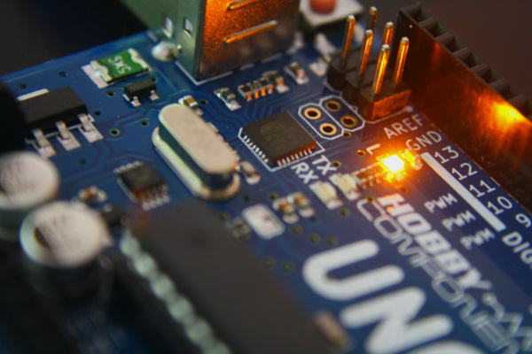
The amber LED shown in the above image of an Arduino Uno is the one we will be controlling.

In the above line of code we create a variable called ‘led’ (marked in green) and the value 13, which represents the pin number our LED is connected to. When we need to know what pin number we are controlling later in our program we can just reference this variable to see what it is. In C++ we can store different types of information, such as numbers, letters, sentences etc. In comparison to a desktop computer, microcontrollers like the ones used in Arduino’s generally have very limited memory space. So in C++ when we create a variable to store some information, we also need to tell it what kind of information we are storing so that can allocate correct amount of memory to hold the information. In our line of code we just want to store a simple decimal number or ‘integer’ which represents our pin number (13). This is exactly what the part of the line marked in purple is doing. So in one line we are creating a variable, naming it ‘led’, stating that we are going to store an integer number and then storing that number in it.
 This line also has a couple of other benefits which will not be obvious to you at this point. First of all, wherever in our program we need to tell the Arduino which pin number we want to control, instead of just writing ’13’, which doesn’t really give you much information about what pin 13 is, we can write the variable name ‘led’. This instantly makes our program more readable to a human as we can see any line that references this pin is accessing an ‘led’. The other benefit is, say we want to connect our LED to another pin. We can simply change the pin number we are storing in this variable at the top of our program and then any line that uses our variable will then reference the correct pin; We don’t need to change every line. In a small program such as this, it’s not a big deal, but in very large program you will quickly see the advantage.
We are almost done with explaining the first line of code, but there is one last part to this line, the semicolon at the end. When we start a new line, we as humans see this as the start of a new section. However, C++ ignores new lines and will see them as a continuation of the previous line. To tell it that we are actually starting a new line of code, which is nothing to do with the previous line, we put a semicolon at the end. If you take a look at the entire blink sketch you’ll see that most lines have a semicolon at the end. When you first start programming quite often you’ll find that you forget to put the semicolon at the end of the line and this will be the cause of errors in your code.
That’s a lot to take in with just our first line! Let’s now move on to the setup section…
SETUP FUNCTION
The setup section is normally used to initially configure the Arduino before running the main part of the sketch. What we are actually looking at here is something called a ‘function’. It may look and sound complicated but at its very basic a function is just a way of splitting up bits of code into smaller, less complicated, parts. We can then give this segment of code a name and run or ‘call’ it just by using its name. We can create our own functions, but in the Arduino environment there are two special ones it expects to be in every sketch, these are called ‘setup’ and ‘loop’. If they are not in the sketch, when we try to compile the program it will generate an error. The first of these two functions – setup, gets run first and only runs once when the Arduino is first started. So, code we only ever want to run once at the beginning of our sketch gets put in here.
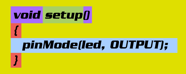
On the first line of our ‘setup’ function we give the function a name (shown above in green). In this case the function is called ‘setup’. Like with our variables, by giving the function a meaningful name we can use this name to call the function whenever we need to run the code inside it.
After the first line we then have an open curly bracket ‘{‘ and a close curly bracket ‘}’ (marked in red). We put any code that we want to run in this function between these two brackets. In our blink sketch there is only one line of code, but there can be as many lines as you require.
Digital Input/Output Pins
On most microcontrollers, including the ones found on Arduino boards, there is usually a set of digital pins that can be controlled from software. They are called digital pins because they can only be in one of two states, high or low. A HIGH represents a voltage on the the pin and a LOW represents no voltage. These in turn can then be connected to the outside world to control things such as relays, LEDs, motors, etc., or to sense the state of things such as switches for example. You can configure these pins to be either an INPUT, allowing you to read the state of something connected to it, or as an OUTPUT, allowing you to control something connected to it.
The line marked in blue is the actual code that we want to run inside the function. In this case we are going to configure the digital pin connected to the LED as an output. Let’s take a closer look at this line:

To configure the pin as an output we use the Arduino command ‘pinMode’ to tell the Arduino we want to configure the pin connected to the LED to be an output. The pinMode command needs two pieces of information, or ‘parameters’, so that it knows which pin to configure and how to configure it. These are passed to the command inside the open ‘(‘ and close ‘)’ brackets and need to be separated by a comma. The first of these two parameters, marked in green, is the pin number we want to control. We could simply write the number 13 for this parameter, but remember at the beginning of the sketch we used the variable ‘led’ to store the correct pin number? So, we can just use that instead. The second parameter specifies whether we want the command to configure the pin as an INPUT or an OUTPUT. Here we want to control the LED from our sketch, so we make the pin an OUTPUT. Notice that because we used the variable we called ‘led’ instead of putting the pin number 13 it makes the line more readable?
Once this command is executed by the Arduino this pin will become an output and will stay as such unless we reset the board or tell it otherwise. As we want this pin to always be an output we therefore only need to run this command once, which is why we have put it in the setup section of our sketch.

The last thing we need to mention about the setup function are the parts marked in purple. We use functions to break up programs into smaller sections, but quite often it is useful to pass pieces of information to and from them. This is not something we need to do in this sketch so we’ll keep things simple in saying that the parts in purple are used for this purpose. The empty brackets shown above mean we wont be passing anything to the function and the word void simply means we won’t be passing anything back out of this function.
Everything is now configured how we want it to be so now we can move on to the main part of our sketch…
The Main Loop
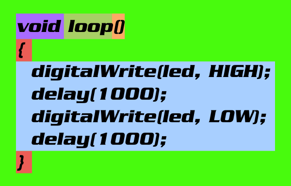
Like the setup function, the main loop is another special function which the Arduino environment expects to be in your sketch. If you compare the above diagram for the loop function with the one for the setup function you’ll see many similarities. If you understood the second line on the setup function you should be able to see that this function is called ‘loop’ and that there are four lines of code inside this function.
Unlike the setup function, which only gets run once at start up, the loop function gets continually run by the Arduino environment. We can therefore put any code we wish to be run repeatedly within this function. This code will run forever, or until you remove the power to the Arduino.
We have already covered the different parts of the function in the setup section so we can move straight on to what the code within our loop function is actually doing…

This is our main program and you’ll notice that it is more or less the same two commands repeated twice. Notice how the format on these commands are very similar to the pinMode command used in the setup function? Marked in purple we have the name of the command. Marked in red are open and close brackets that contain the parameters the command needs to know, and marked in green and orange are the actual parameters. The lines are terminated with semicolons to denote where the commands end.
![]()
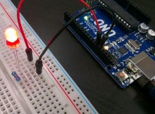
If we look at the first command, ‘digitalWrite’, this command is used to control the state of a digital pin. With this command we can make the pin either HIGH (a voltage, normally +5V) or LOW (no voltage, 0V). In the first command we set the pin HIGH with the parameter marked in orange. We also need to tell the command which digital pin we want to set high, which we do with the parameter marked in green. Again, for this we use our ‘led’ variable.
Once this command is executed the pin becomes high, which powers the LED connected to it and the LED turns on.
![]()
![]()
You may have already guessed what the second command ‘delay’ may do from its name. It tells the Arduino to wait for a set period of time. The number between the brackets is the amount of time in milliseconds. 1000ms = 1 second, so we tell the Arduino to wait for 1 second before moving to the next command. The Arduino will simply do nothing for one second. After a one second wait we run another digitalWrite command but this time we use the command to set the pin LOW. This has the effect of turning the LED off.
![]()
The last line is another delay command and is identical to the first delay command, causing the Arduno to wait for another second.
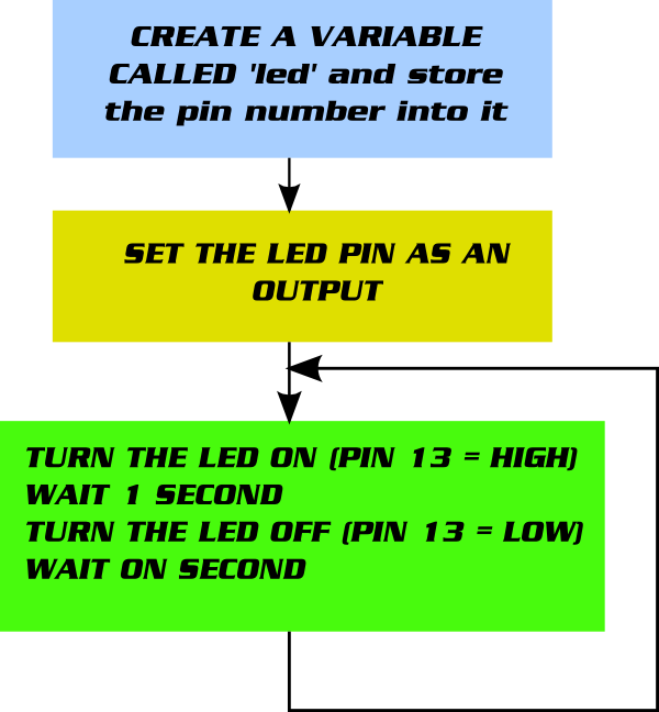
So to summarise, our main program turns the LED on, waits one second, turns the LED off, and waits another second. At the end of this sequence our program gets to the end of our loop function and the Arduino automatically runs it over and over again. This has the effect of causing the LED to be turned on and off repeatedly at 1 second intervals, giving the effect of a blinking LED.
Here is a final summary…..
Check out our guide for installing the Arduino software and this tutorial for testing the blink sketch.

Just wanted to say thanks for this post.
Really helpful in learning the most basic command structure.
I hope by searching the rest of your blog I can find similar articles that explain the functions so well.
My experience of programming is very limited, I have an application to work towards but can’t find anywhere local (WMidlands) to do a course etc, so as a customer too, your blog is helping an awful lot.
Thanks for the feedback. We will try to post more tutorials whenever we can find time to do it.
This is so straight forward and helpful. I originally start to learn programming in basic, were I kept my programs on paper tape. But I have found difficulty, in working without flow diagrams. I might find it easier. If in the multifunction board, itwasin the form of a flow diagram were perhaps, the command push a keyCould direct me to three different “is it loop or main program “ , perhaps :
1. Blink a led on pin 5.
2. Read voltage of potentiometer 0 – 1023, and in volts
3. Read voltage of sensor connected to A5
I have noticed in the key press it shows two pin read statement, so perhaps.
I could develope the program to
12 pressed gives display voltage on 7 segments of potentiometer value
13 pressed gives display voltage of a5 on 7 segments