


Arduino development boards are great devices for embedded control. At the low end are the low cost ATMega328 based Arduinos, such as the Uno, Nano, and Pro Mini. At the other end of the scale there are the high priced but more powerful Arm based devices, such as the Due. But sometimes your application may call for a board with the power of an Arm based device but with the low end cost of a Pro Mini or Nano. In these cases there are of course a large range of alternative microcontrollers; however, these tend to be aimed at the more experienced user and require a deeper understanding of the inner workings of both the microcontroller and their programming tools (IDE).
In recent updates to the Arduino IDE one big improvement they have made to their software is the ability to add unofficial third party development board support via the new ‘board manager’ feature. This feature has now opened up the ease and simplicity of the Arduino IDE to alternative microcontrollers. We’ve already seen a big increase in popularity of the Espressif ESP8266 based boards due to support being added to the Arduino IDE and now the same is true for the powerful ST Microelectronics STM32 Arm based microcontrollers. These microcontrollers are not only far more powerful than a standard Arduino, but a basic development board can be purchased for around the price a low end Arduino, such as pro micro. In the table below you can see for yourself how the two similarly priced boards compare:
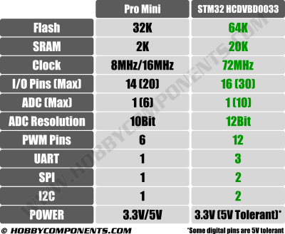
In this tutorial we’ll show how to quickly set up your Arduino IDE, test your setup and upload the standard ‘blink sketch’ to the STM32. Note that although this guide can be applied to many ST32 variants, it has been written for the STM32 HCDVBD0033 (aka ‘black pill’) development board.
To follow the guide you will need:
An STM32 development board such as this one:Â HCMODU0033 STM32F103C8T6 (Black pill) Development Board available here.
A USB to serial to 3.3V TTL adaptor such as this one:Â HCMODU0051 CP2102 3.3V USB to serial port adapter available here.
The Arduino IDE which is available to download for free here.
Step 1) Adding support to the Arduino IDE:
The first thing we’ll need to do is to tell the Arduino IDE where to download the support files for the STM32. In your IDE go to File→Preferences…

A new window will open up. In this window you will see a text box labelled ‘Additional Boards Manager URLs’. In this text box we need to paste the URL from where the Arduino IDE can download the additional board support files for the STM32.
Credit: These files have been kindly provided by Dan Drown (http://dan.drown.org).
Cut and paste the line below into this text box:
http://dan.drown.org/stm32duino/package_STM32duino_index.json
If there are any previous URLs listed, just add the above line and separate it with a comma.
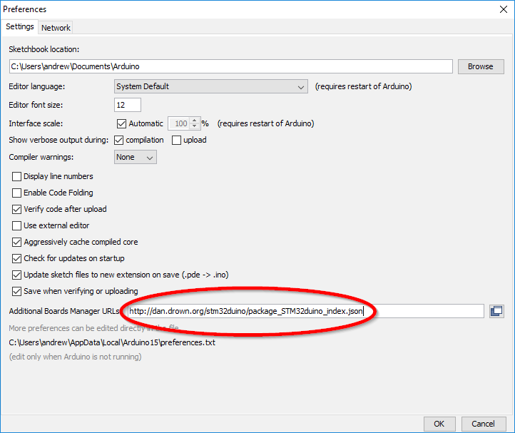
You can now close this window by clicking the OK button.
In the top menu bar, select Tools→ Board → Board manager
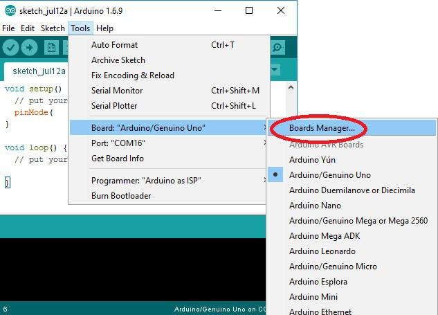
A new window will open with a list of supported add-ons. Find the package titled ‘STM32F1xx/GD32F1xx boards by stm32duino version xxxx.x.xx’
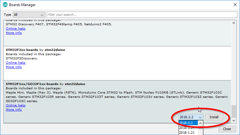
Next, click on this package and in the bottom right hand corner you will see a version drop-down selection box and an install button appear. Make sure the latest version is selected and then click the install button.
The Arduino IDE will now start installing the package. Depending on your internet connection speed this may take a few minutes.
Once completed you can close the board manager window and return back to the main Arduino IDE.
Important: You will need to restart the IDE otherwise you’ll get a compile error. Once restarted go to Tools → Board and you will now see additional board options for STM32 based development boards under the heading ‘STM32 Boards (STM32Duino.com)’. Select the appropriate board option for your development board. For the board used in this guide select ‘Generic STM32F103C series’. Under ‘Tools’ your board settings should now look like this:
Board: “Generic STM32F103C series”
Variant: “STM32F103C8 (20k SRAM, 64k Flash)”
CPU Speed (MHz): “72MHz (Normal)”
Upload method: “Serial”
Optimize: “Smallest (default)”
Step 2) Connecting your hardware:
The Arduino IDE can program the ST32 development board via its serial port just like programming a Pro Micro. To do this you will first need to connect your USB adapter to the board. For the development board used in this example the serial adapter can be connected as follows:
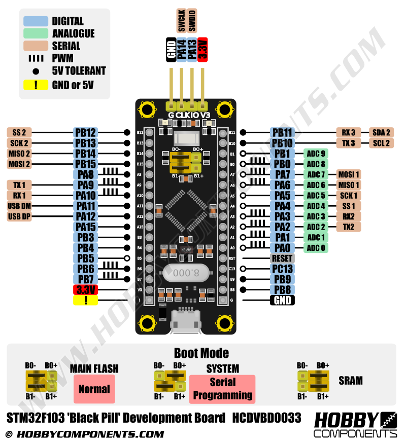
Now plug your USB adapter into your computer and select its COM port via Tools → Port. One final step before we can upload a sketch is to put the board into its bootloader mode so that it can accept the uploaded sketch via its serial port. To do this put the yellow B0 jumper into the B0+ position (see above image). The jumper must be kept in this position when programming the board. Once the sketch has finished uploading it will automatically run. However if at any point the board is reset or power removed whilst the jumper is in this position the uploaded sketch will be erased. To stop this from happening you must put the B0 jumper back in its B0- position.
Step 3) Uploading the blink sketch:
With the Arduino IDE set up and the development board connected to your computer you can now upload the blink test sketch. So that we can see the sketch running we’ll use the pin connected to the on-board LED which is connected to digital pin PB12. You can use the modified blink sketch below. Just cut and paste it into the Arduino IDE window.
#define LED_PIN PB12
void setup()
{
pinMode(LED_PIN, OUTPUT);
}
void loop()
{
digitalWrite(LED_PIN, HIGH);
delay(1000);
digitalWrite(LED_PIN, LOW);
delay(1000);
}
If everything is set up correctly it should now be a simple case of uploading the sketch by clicking the IDEs ‘Upload button’. If all goes well the IDE will compile the sketch and upload it to the board and the on-board LED will start blinking.
You have now successfully configured and programmed your development board via the Arduino IDE. Note that this sketch is making use of the standard Arduino digital pin commands to configure and control the GPIO pin 2. You can use many of the built in commands contained within the Arduino IDE to control features of this development board in the same way you would if you were using an ordinary Arduino development board.


Nice little board.
Works.
I’m trying to use this black pill with the micro SD card reader module. I have the SD card reader working on the Arduino UNO, but I can’t get it to work on the Black pill. Can anyone show how to do this? Thanks.
Just for further information I’m using PA7 for MOS!, PA6 for MISO, PA5 for Clk, and PA4 for CS. I’ve tried hooking the Card Reader module up to 3.3v VCC and when that didn’t work I hooked it up to 5v VCC since it has 3.3v buffers for the rest of the connections to the Black Pill. But I couldn’t get it to recognize the SD card.
Thanks.
Whoops! Never mind, I got it working now. Turned out to be an electrical connection failure. I thought I was making some sort of programming error. Sorry about that.
Hey James, can show me the code of got the sd working with the black pill ? I am trying it with the blue pill but I am not able to get it working. Thank you.
The youtube video “A Micro SD Adapter interfaced to a STM32 as used in the LotBot Base Project” in youtube channel “LotBot Robotics” shows how to use an SD Card Module with a blue pill.