Although you may have never heard of the ESP8266, it has quietly been a huge success in the microcontroller world due to it’s impressive spec and incredibly low price. It is a small wireless microcontroller with built in Wi-Fi (802.11) capability, meaning that it can not only connect to most Wi-Fi access points, but is also capable of becoming it’s own Wi-Fi hotspot, thus allowing other devices to connect to it. This means for a few pounds you can have a remote sensor/controller that has access to the internet via a standard WiFi wireless connection.
The ESP8266 comes in many forms from simple modules to full development boards. Most will come pre-flashed with firmware allowing it to be used as a simple slave device, giving other microcontrollers, such as an Arduino development board, Wi-Fi capability (see our previous blog post here http://blog.hobbycomponents.com/?p=165). But packed into this little device is an ARM processor which is more powerful than most Arduino’s that it will often get connected to. It is in itself a fully fledged development platform and doesn’t need to be slaved to any other device.
Their immediate popularity has meant there has been a lot of development for these devices, part of which has resulted in third party compatibility with the Arduino Integrated Development environment (IDE). With a simple add-on you can configure the Arduino IDE to directly support and program theses devices just as if they were an ordinary Arduino. This means that if you are already familiar with programming Arduino’s, you can quickly get up and running with the ESP8266.
This guide will show you how to quickly set up your Arduino IDE for the ESP8266 and then use it to write and upload your first sketch.
WARNING: This guide will overwrite any existing firmware within your ESP8266. It does not cover how to restore any existing firmware. You should therefore only follow this guide if you only wish to use the ESP8266 with the Arduino IDE.
Requirements:
You will of course require either an ESP8266 module or development board. We currently recommend one of the two following boards and this guide will be focusing on them:
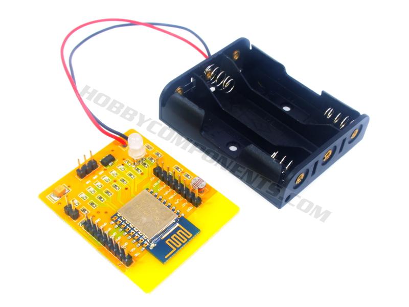
ESP 8266 development board (HCDVBD0027).
ESP8266-D1 Arduino compatible development board (HCDVBD0028).
To program your ESP8266 via the Arduino IDE you will need to be able to connect it to your PC’s USB port. If your development board or module doesn’t have a USB interface then you’ll need an additional adaptor which will connect from the PC’s USB port to serial interface on the ESP8266. One important thing to note is that the ESP8266’s serial interface, and its GPIO, are not 5V tolerant. This means you should not connect anything above 3.3V to any of its digital pins, including its serial interface. Therefore we recommend using our CP2102 3.3V USB interface adaptor (HCMODU0051) which can be purchased via our shop here:
http://hobbycomponents.com/usb-interface/396-usb-to-uart-serial-interface-module-adaptor
Installing and configuring the Arduino IDE
The latest versions of the Arduino IDE now provide the ability to add third party hardware support which includes support for the ESP8266 in various forms. We recommend downloading the very latest version of the IDE (V1.6.9 at the time of writing this post). It can be downloaded from the downloads section of the Arduino website here:
https://www.arduino.cc/en/Main/Software
Make sure that you download the last version for your operating system. If you’ve not installed the IDE before you can find a guide on how to do this in a previous blog post here:
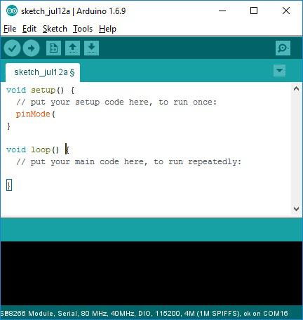
Once installed, launch the IDE and you will be presented with a default blank editing window:
Before we can use the IDE to program your ESP8266 we need to add third-party EPS8266 support. We can easily do this with just a few mouse clicks via the IDE’s build in ‘board manager’ feature:
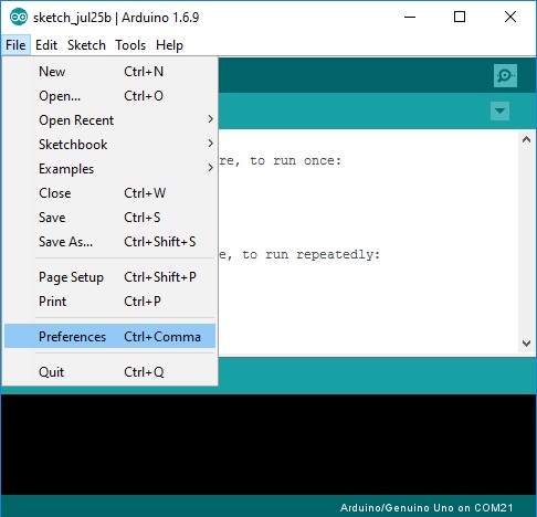
In the top menu bar select File->Preferences…
A new window will open up. In this window you will see a text box labeled ‘Additional Boards Manager URLs’. In this text box we need to paste the URL from where the Arduino IDE can download the additional board files for the ESP8266. These files have been very kindly provided by the ESP8266 community forum (http://esp8266.com). Cut and past the line below to this text box:
http://arduino.esp8266.com/stable/package_esp8266com_index.json
If there are any previous URLs there just add the above line and separate it with a comma.
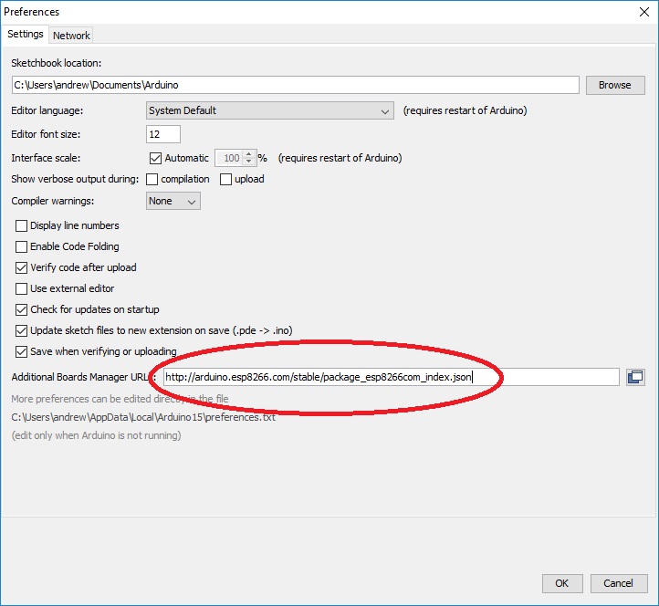
You can now close this window by clicking the OK button.
In the top menu bar select Tools->Board-> Board Manager…
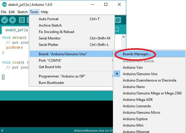
A new window will open with a list of supported add-ons. Find the package titled ‘esp8266 by ESP8266 Community’. You may have to scroll down to the bottom of the list to find it.
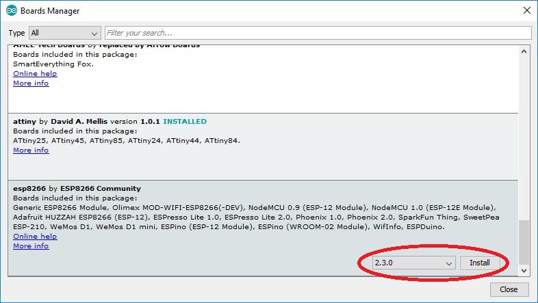
Next, click on this package and in the bottom right hand corner you will see a version drop-down selection box and an install button appear. Make sure the latest version is selected and then click the install button.
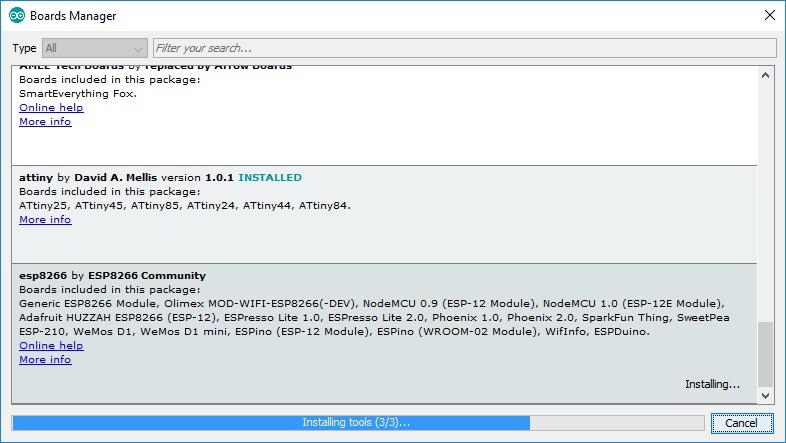
The Arduino IDE will now start installing the package. Depending on your internet connection speed this may take a few minutes.
Once completed you can close the board manager window and return back to the main Arduino IDE.
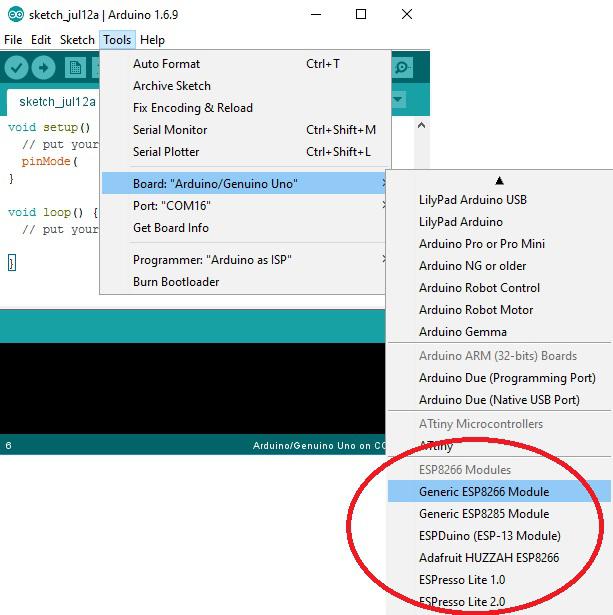
You will now find there are additional board options for the ESP8266 under Tools->Board.
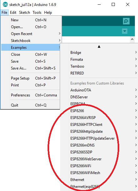
As well as new board options being added to the IDE, the ESP8266 package adds a number of example sketches ranging from a basic blink sketch to advanced webservers.
Setting up your ESP8266
There are a large range of boards and modules based on the ESP8266 and the methods for programming them vary slightly. Therefore the following example will concentrate on the ESP8266E development board (HCDVBD0027) and the ESP8266-D1 Arduino compatible development board (HCDVBD0028).
ESP8266E development board (HCDVBD0027)
For more information about this development board see the following thread on our support forum here:
http://forum.hobbycomponents.com/viewtopic.php?f=110&t=2056
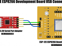
To connect the ESP8266E development board to your computer you will need a USB to serial interface adaptor. The adaptor we recommend is the CP2102 (HCMODU0051) which is specifically designed to interface to devices with 3.3V logic levels.
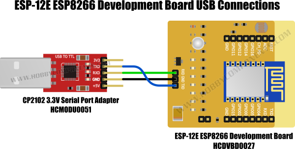
Connect the adapter as shown in the above diagram. Note that Tx on the module connects to Tx on the development board and similarly Rx connects to Rx. The grounds of both devices must also be connected.
As with most ESP8266 devices, before we can upload a sketch into the development board we need to put the board into ‘programming mode’. We do this by applying power to the board with a jumper inserted into the development boards programming header (by default this jumper should be supplied already inserted into the programming header).
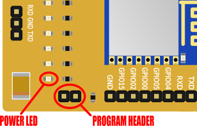
This development board uses batteries as a power source, but it can alternatively be powered by an external 3.3V supply connected to the boards VCC pin. With either option, power up the development board.
With power applied you should see the power LED illuminate. Additionally the RGB LED will also glow a blue-green colour. This signifies that the board is now in programming mode.
If you haven’t already, connect the USB adaptor to your computer.
We now need to configure the Arduino IDE for this development board. In the IDE go to the Tools menu and configure the settings so they match the ones in the image below:
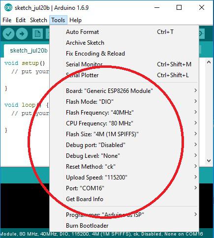
Note that the ‘Port’ setting needs to be set to whatever COM port is assigned to your USB interface adapter.
The Arduino IDE is now all ready to upload a sketch to your board. You can now jump forward to the Blink test part of this guide.
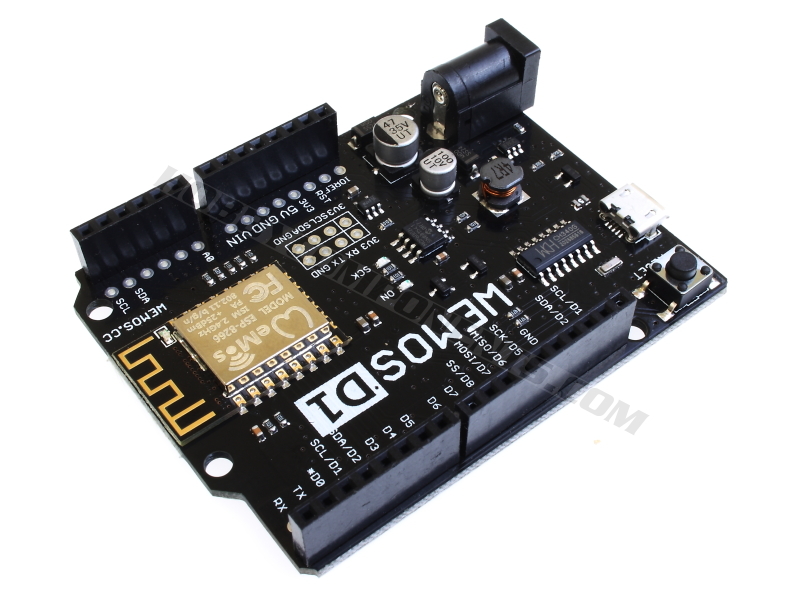
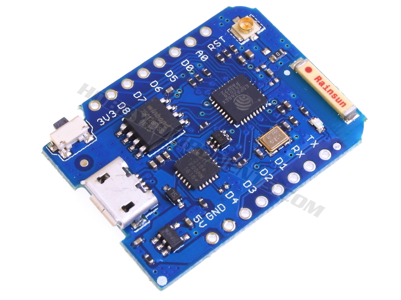
WeMos D1 (HCWEMO0001) & D1 Mini Pro (HCWEMO0002) development boards.
For more information about these development boards see the WeMos section in our support forum here:
http://forum.hobbycomponents.com/viewforum.php?f=111
The WeMos D1 & D1 Mini Pro are programmed via their micro USB port so connection to your computer is as simple as connecting a USB cable.
You will however need to install a special USB driver. The WeMos D1 uses a CH340 USB to serial device for its USB interface whereas the WeMos D1 mini Pro uses a Silicon Labs CP2104 USB to UART IC. This means that the USB driver you will need to install will depend on which of these two boards you are using.
For the WeMos D1 you can download the latest driver from our support forum here:
http://forum.hobbycomponents.com/viewtopic.php?f=111&t=2125
For the WeMos D1 Mini Pro you can find the link here:
http://forum.hobbycomponents.com/viewtopic.php?f=111&t=2126
Simply download and unzip the file, plug in your WeMod D1/D1 mini Pro and when the new hardware is detected, point the wizard to the folder you just unzipped to and it should install without any problems. When the driver installs, it will assign a ‘COM’ port to the ESP8266-D1. Make a note of the port number as it will be needed when configuring the board settings in the Arduino IDE.
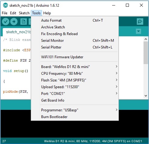
Next, in the Arduino IDE go the tools menu and configure the Board, CPU Frequency, Flash Size and Upload Speed as shown above. Additionally, set the Port to match whatever COM port number was assigned when installing the drivers.
The Arduino IDE is now all ready to upload a sketch to your board. You can now move on to the Blink test part of this guide.
Blink Example:
With everything configured correctly we should now be able to upload a sketch into the development board. Cut and paste the following example ‘blink’ sketch into the Arduino IDE window, making sure you replace any existing code in the window with the example sketch.
[cpp]
/* Blink example – HobbyComponents.com */
#include <ESP8266WiFi.h>
#define PIN 2 // Flash the LED connected to GPIO2
void setup()
{
pinMode(PIN, OUTPUT); // Set the pin to an output
}
void loop()
{
digitalWrite(PIN, LOW); // Turn the LED on
delay(1000); // Wait for a second
digitalWrite(PIN, HIGH); // Turn the LED off
delay(1000); // Wait for another second
}[/cpp]
Next upload the sketch by clicking the Arduino IDEs upload button (round icon with a right pointing arrow found in the top-left corner of the window). If everything is configured correctly the IDE will compile the sketch and upload it to the development board. This will normally take between 15 to 30 seconds depending on the speed of your computer. Whilst uploading you may see several LEDS blink rapidly on both the development board and/or the USB interface.
When programming has completed you should see the blue LED on the WeMos will blink slowly. For the WeMos D1 both the red GPIO 2 LED and the blue module LED should now blink at a rate of once per second. For the ESP8266E development board an additional red LED on the development board itself will also blink.
You have now successfully configured and programmed your development board via the Arduino IDE. Note that this sketch is making use of the standard Arduino digital pin commands to configure and control the GPIO pin 2. You can use many of the built in commands contained within the Arduino IDE to control features of this development board in the same way you would if you were using an ordinary Arduino development board.